
Use and Care Manual


ASSEMBLY & ADJUSTMENTS
WARNING: To prevent injury from accidental operation, make sure the tool is switched OFF and un-
plugged from the power source before assembling or making any adjustments.
CLEANING THE MACHINE
Your tool comes protected with a layer of anti-rust coating. Wipe off the coating using an acetone-moistened
cloth. DO NOT use cellulose-based solvents such as paint thinner or lacquer thinner, as these will damage the
painted surfaces. Then, apply a light coat of good-quality paste wax onto surfaces to protect from rust and corro-
sion.
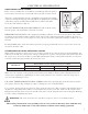
MOUNTING THE LATHE TO A BENCHTOP
For safe operation, securely mount the lathe onto a secure workbench to prevent movement during operation
(mounting hardware is not included). Refer to the graph below (Fig. 1) for your lathe’s base dimensions.
NOTE: If the machine is not being mounted onto a benchtop, install the 4 rubber feet into the mounting holes.
855 mm
185 mm
M8x15 mm
9
Fig. 1
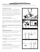
Fig. 2
TOOL REST ADJUSTMENTS (FIG. 2)
You can adjust the position, height and angle of the tool rest as-
sembly to suit your task at hand.
1. The tool rest locking lever (Fig. 2 - 1) locks the tool rest body
(Fig. 2 - 2) in position. Loosen the lever to slide the tool rest body
along the lathe bed. Tighten the lever firmly when the tool rest
body is properly positioned.
NOTE: There is a nut on the underside of tool rest body that
needs to be tightened periodically to enable the tool rest body
locking lever to tighten properly.
2. The small tool rest locking handle (Fig. 2 - 3) locks the tool rest
(Fig. 2 - 4) in place. Loosen the handle to position the tool rest at
the specific angle or height. Tighten the handle firmly when the
tool rest is properly positioned.
2
1
3
4
NOTE: Adjust the height of the tool rest to just below the center of the workpiece, so that the tool will cut at the
center of the workpiece (see page 14).