MODEL 34035 14" x 20" VARIABLE SPEED WOOD LATHE Instruction Manual NEED HELP? CONTACT US! Have product questions? Need technical support? Please feel free to contact us: 1-800-232-1195 (M-F 8AM-5PM CST) TECHSUPPORT@WENPRODUCTS.COM IMPORTANT: Your new tool has been engineered and manufactured to WEN’s highest standards for dependability, ease of operation, and operator safety. When properly cared for, this product will supply you years of rugged, trouble-free performance.
CONTENTS WELCOME 3 Introduction...................................................................................................... 3 Specifications.................................................................................................... 3 SAFETY 4 General Safety Rules......................................................................................... 4 Specific Rules for Your Lathe............................................................................ 6 Electrical Information...
INTRODUCTION Thanks for purchasing a WEN Lathe. We know you are excited to put your tool to work, but first, please take a moment to read through the manual. Safe operation of this tool requires that you read and understand this operator’s manual and all the labels affixed to the tool. This manual provides information regarding potential safety concerns, as well as helpful assembly and operating instructions for your tool. SAFETY ALERT SYMBOL: Indicates danger, warning, or caution.
GENERAL SAFETY RULES WARNING! Read all safety warnings and all instructions. Failure to follow the warnings and instructions may result in electric shock, fire and/or serious injury. Safety is a combination of common sense, staying alert and knowing how your item works. The term “power tool” in the warnings refers to your mains-operated (corded) power tool or battery-operated (cordless) power tool. SAVE THESE SAFETY INSTRUCTIONS. WORK AREA SAFETY 6. If operating a power tool in a damp location is 1.
GENERAL SAFETY RULES WARNING! Read all safety warnings and all instructions. Failure to follow the warnings and instructions may result in electric shock, fire and/or serious injury. Safety is a combination of common sense, staying alert and knowing how your item works. The term “power tool” in the warnings refers to your mains-operated (corded) power tool or battery-operated (cordless) power tool. SAVE THESE SAFETY INSTRUCTIONS. 7.
SPECIFIC RULES FOR YOUR LATHE WARNING! Do not operate the power tool until you have read and understood the following instructions and the warning labels. TURNING SAFETY 1. This lathe is designed and intended for use by properly trained and experienced personnel only. If you are not familiar with the proper and safe operation of a lathe, do not use it until proper training and knowledge have been acquired. 2. DO NOT wear loose clothing or jewelry.
SPECIFIC RULES FOR YOUR LATHE WARNING! Do not operate the power tool until you have read and understood the following instructions and the warning labels. PREPARING THE LATHE 3. Ensure hands are away from the turning area. 1. When transporting the lathe, carry it by the base or handles. Never carry the device by its guards or its ac- 4. If you are interrupted when operating the lathe, complete the process and switch the lathe OFF before lookcessories. ing up. 2.
ELECTRICAL INFORMATION GROUNDING INSTRUCTIONS In the event of a malfunction or breakdown, grounding provides the path of least resistance for an electric current and reduces the risk of electric shock. This tool is equipped with an electric cord that has an equipment grounding conductor and a grounding plug. The plug MUST be plugged into a matching outlet that is properly installed and grounded in accordance with ALL local codes and ordinances. 1. Do not modify the plug provided.
UNPACKING & TRANSPORTATION WARNING! Do not plug in or turn on the tool until it is fully assembled according to the instructions. Failure to follow the safety instructions may result in serious personal injury. UNPACKING With the help of a friend or trustworthy foe, carefully remove the Lathe from the packaging. Make sure to take out all contents and accessories. Do not discard the packaging until everything is removed. Check the packing list below to make sure you have all of the parts and accessories.
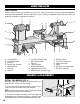
KNOW YOUR LATHE TOOL PURPOSE Lathes are tools that turn your workpiece so you can cut, shape, and sand them. Refer to the following diagrams to become familiarized with all the parts and controls of your Lathe. The components will be referred to later in the manual for assembly and operation instructions. J E F G D H K I C L B M A P O R T A. B. C. D. E. F. G. N Q S Lower Belt Door Handle/Tool Holder Headstock Spindle Lock (on back) Upper Belt Door Face Plate Tool Rest H. I. J. K. L. M. N.
ASSEMBLY & ADJUSTMENTS WARNING! Do not plug in or turn on the tool until it is fully assembled according to the instructions. Read through and become familiarized with the following procedures of handling and adjusting your tool. Failure to follow the safety instructions may result in serious personal injury. Fig. 3 185 mm M8-1.25x15mm 855 mm REMOVE THE ANTI-RUST COATING Tool comes protected with a layer of anti-rust coating that needs to be cleaned off before use.
ASSEMBLY & ADJUSTMENTS INSTALL THE FACE PLATE Fig. 5 When installing the face plate for turning bowls and plates, mount the workpiece onto the face plate prior to installing the face plate on the headstock (see "Mount The Workpiece Onto The Face Plate" on page 19). To install the face plate: 1. Thread the face plate (Fig. 5 - 4) onto the headstock spindle by turning it clockwise as far as it will go, and then tighten the two set screws (Fig. 5 - 5) with a hex wrench. 2 3 1 4 5 2.
ASSEMBLY & ADJUSTMENTS ADJUST THE TAILSTOCK Fig. 9 1. Loosen the tailstock locking lever (Fig. 9 - 3) and slide the tailstock along the lathe bed into the desired position. Retighten the locking lever. 2. Loosen the quill locking handle (Fig. 9 - 2) just enough to unlock the tailstock quill. Turn the handwheel (Fig. 9 - 1) clockwise to advance the quill and counterclockwise to retract the quill. Retighten the quill locking handle.
ASSEMBLY & ADJUSTMENTS ADJUST THE SPEED Fig. 13 Your variable speed lathe has three speed ranges: Low 250-720 RPM, Medium 600-1700 RPM, and High 12003550 RPM. Always start at slower speeds for rough cuts and larger workpieces. Use faster speeds for refined cuts and detailed work. 1 Set the suitable speed range for your operation by adjusting the belt position. Change the speed within a speed range using the speed adjustment knob. The speed will be displayed on the digital RPM readout (Fig.
OPERATION TURNING TOOLS If possible, select only quality high-speed steel turning tools. High-speed steel tools hold an edge and last longer than ordinary carbon steel. As one becomes proficient in turning, a variety of specialty tools for specific applications can be acquired. The following tools provide the basics for most woodturning projects. Smoothing Bowls 45° Bevel Turning Rough Stock Round 1. ROUGHING GOUGE - use this tool to shape square or out-of-round spindle-turning stock into a cylinder.
OPERATION WARNING! Do not plug in or turn on the tool until it is fully assembled according to the instructions. Read through and become familiarized with the following procedures of handling and adjusting your tool. Failure to follow the safety instructions may result in serious personal injury. MOUNT THE WORKPIECE BETWEEN SPINDLES Spindle turning takes place between the centers of the lathe, with the workpiece being held between the spur center in the headstock and the live center in the tailstock.
OPERATION NOTE: The following operation instructions serves as a beginning point for some common lathe operations. Practice on scrap material to become familiarized with the operation process and make the necessary adjustments before working on your workpiece. SPINDLE TURNING - ROUGHING OUT CUT Roughing out is the first step of the lathe operation, which uses the large roughing gouge tool to smooth out sharp corners to make the workpiece cylindrical.
OPERATION SPINDLE TURNING - CREATING BEADS Making a parting cut for the desired depth and location of your bead. 1. Place the parting tool on the tool rest and move the tool forward to make the full bevel of the tool come into contact with the workpiece. Gently raise the handle to make cuts of the appropriate depth. Repeat for the other side of the bead. 2. Using a small skew or spindle gouge, start in the center between the two cuts and cut down each side to form the bead.
OPERATION SPINDLE TURNING - SANDING THE WORKPIECE Adjust the lathe to a slower speed for sanding and finishing. High speed can build friction while sanding and cause burns in some woods. The cleaner the cuts, the less sanding will be required. So try to make the cuts as refined as you can before moving to the sanding process. 1. Use sandpaper finer than 120 grit, as coarse sandpaper may scratch the workpiece. Fold the sandpaper into a pad will allow easier and safer sanding.
OPERATION TO SHAPE THE INSIDE OF A BOWL OR PLATE Turn off the lathe and move the tailstock out of the way. Mount the workpiece onto the face plate and install the face plate onto the headstock (see "Install The Face Plate" on page 12). Adjust the tool rest in front of the workpiece to be just below the centerline and at the right angle to the lathe’s turning axis. Rotate the workpiece by hand to check for proper seating and clearance.
TROUBLESHOOTING GUIDE WARNING! Stop using the tool immediately if any of the following problems occur. Repairs and replacements should only be performed by an authorized technician. For any questions, please contact our customer service at (800) 232-1195, M-F 8-5 CST or email us at techsupport@wenproducts.com. PROBLEM Motor will not start. Motor or spindle stalls. Excessive vibration. Tools grab or dig in. Tailstock or tool rest base moves when locked and pressure is applied. Error code shown.
MAINTENANCE WARNING! To avoid accidents, turn OFF and unplug the tool from the electrical outlet before cleaning, adjusting, or performing any maintenance work. WARNING! Any attempt to repair or replace electrical parts on this tool may be hazardous. Servicing of the tool must be performed by a qualified technician. When servicing, use only identical WEN replacement parts. Use of other parts may be hazardous or induce product failure.
EXPLODED VIEW & PARTS LIST NOTE: Not all parts may be available for purchase. Parts and accessories that wear down over the course of normal use are not covered under the warranty.
EXPLODED VIEW & PARTS LIST 24 No. 1 Part No. 34034-001 Qty. 4 34034-004 Description Foot Belt Tension Lock Lever, M8x20 Washer, 8mm No. 47 Part No. 34034-047 Description Set Screw, M8x10 Qty.
WARRANTY STATEMENT WEN Products is committed to building tools that are dependable for years. Our warranties are consistent with this commitment and our dedication to quality. LIMITED WARRANTY OF WEN PRODUCTS FOR HOME USE GREAT LAKES TECHNOLOGIES, LLC (“Seller”) warrants to the original purchaser only, that all WEN consumer power tools will be free from defects in material or workmanship during personal use for a period of two (2) years from date of purchase or 500 hours of use; whichever comes first.
NOTES 26
NOTES 27
THANKS FOR REMEMBERING V. 2021.03.