2-INCH VARIABLE SPEED WOOD LATHE Model # 3427 bit.ly/wenvideo IMPORTANT: Your new tool has been engineered and manufactured to WEN’s highest standards for dependability, ease of operation, and operator safety. When properly cared for, this product will supply you years of rugged, trouble-free performance. Pay close attention to the rules for safe operation, warnings, and cautions. If you use your tool properly and for intended purpose, you will enjoy years of safe, reliable service.
TABLE OF CONTENTS Technical Data General Safety Rules Specific Safety Rules For Wood Lathes Electrical Information Know Your Wood Lathe Assembly Adjustments Operation Maintenance Troubleshooting Guide Exploded View & Parts List Warranty 2 3 4 5 6 6 10 11 17 17 18 20 TECHNICAL DATA Model Number: Motor: Swing Over Bed: Distance Between Centers: Speeds: Spindle Taper: Tailstock Taper: Tool Rest Length: Dimensions: Weight: 2 3427 120 V, 60 Hz, 4.5A, S6 40% 12 in. 15-3/4 in. 500 to 2500 RPM MT2 MT2 7-7/8 in.
GENERAL SAFETY RULES Safety is a combination of common sense, staying alert and knowing how your item works. SAVE THESE SAFETY INSTRUCTIONS. WARNING: To avoid mistakes and serious injury, do not plug in your tool until the following steps have been read and understood. 1. READ and become familiar with this entire instruction manual. LEARN the tool’s applications, limitations, and possible hazards. 2. AVOID DANGEROUS CONDITIONS. Do not use power tools in wet or damp areas or expose them to rain.
GENERAL SAFETY RULES 15. DO NOT OVERREACH. Keep proper footing and balance at all times. Wear oil-resistant rubber-soled footwear. Keep the floor clear of oil, scrap, and other debris. 16. MAINTAIN TOOLS PROPERLY. ALWAYS keep tools clean and in good working order. Follow instructions for lubricating and changing accessories. 17. CHECK FOR DAMAGED PARTS. Check for alignment of moving parts, jamming, breakage, improper mounting, or any other conditions that may affect the tool’s operation.
ELECTRICAL INFORMATION GROUNDING INSTRUCTIONS IN THE EVENT OF A MALFUNCTION OR BREAKDOWN, grounding provides the path of least resistance for an electric current and reduces the risk of electric shock. This tool is equipped with an electric cord that has an equipment grounding conductor and a grounding plug. The plug MUST be plugged into a matching outlet that is properly installed and grounded in accordance with ALL local codes and ordinances. DO NOT MODIFY THE PLUG PROVIDED.
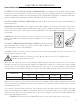
KNOW YOUR WOOD LATHE A B C D E F G H I J K L M N O Power Switch E Variable Speed Knob Digital Readout Headstock Back Face Plate Spindle Lock D Gauge Center Spur Tool Rest Live Center C Tailstock Handwheel Tailstock Tool Rest Locking Handle Motor B Directional Rotation Switch F G H J I K L O A N M ASSEMBLY UNPACKING Carefully unpack the lathe and all its parts. Compare against the list below. Do not discard the carton or any packaging until the lathe is completely assembled.
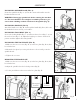
ASSEMBLY 1 INSTALLING SPINDLE LOCK (FIG. A) Locate the spindle lock (Fig. A - 1) from the carton and install it onto the headstock with a wrench. WARNING: Disengage spindle lock before turning the machine on. The lock should be in it’s highest available position to prevent it from colliding with the rotation of the spindle (Fig. E). INSTALLING HANDLE (FIG. B) Attach the handle screw (Fig. B - 2) through the handle (Fig. B - 1) hole onto the handwheel. Secure it using a screwdriver. Fig.
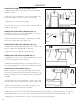
ASSEMBLY INSTALLING THE SPUR CENTER (FIG. F) 1. Make sure the surfaces of both the spur center and the spindle are clean. 1 2 2. Drive the spur center (Fig. F - 1) into the workpiece (Fig. F - 2) using a rubber mallet or a piece of scrap wood. 3. Push the spur center into the spindle Fig. F Note: It is not necessary to remove the face plate in order to install the spur center. REMOVING THE SPUR CENTER (FIG. G) 1. Hold spur center to prevent it from falling.
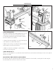
ASSEMBLY 1 1 2 4 5 3 6 Fig. L Fig. J INSTALLING BED EXTENSION (FIG. K) (SOLD SEPARATELY) The WEN 3427EX1 Wood Lathe Bed Extension is an optional accessory that can be purchased separately to extend the maximum length of the lathe’s capacity from 15.75 inches to 39.4 inches. 1 2 1. Fit the bed extension (Fig. K - 3) to the bed using four socket head screws and four flat washers. 2. Remove the end stop screw (Fig. K - 2) from the bed and assemble it onto the bed extension. 3.
ADJUSTMENTS TOOL REST ADJUSTMENTS Users can adjust the height, position and angle of the tool rest assembly. Loosen the locking lever (Fig. M - 1) on the tool rest base to slide the base forward and back or to adjust the angle of it. Tighten the locking lever firmly before operating the lathe. Loosen the small locking handle (Fig. M - 2) to raise and lower the tool rest or to also adjust its angle. Tighten the handle before operating the lathe.
OPERATION OPERATING CONTROLS (FIG. P) 1. Digital speed display - shows the current speed (RPM) of the spindle. 2. Protection Indicator - if the machine turns off and the protection indicator light begins to blink, it means that the motor was protected from overload. The workpiece may be too big or heavy for the current speed of the lathe. To reset it: - Turn off the main switch. - Wait two seconds and then turn it back on. - Work carefully and reduce the depth of the cut.
OPERATION TURNING TOOLS If possible, select only quality high-speed steel turning tools. High-speed steel tools hold an edge and last longer than ordinary carbon steel. As one becomes proficient in turning, a variety of specialty tools for specific applications can be acquired. The following tools provide the basics for most woodturning projects. 12 1. Large roughing gouge - use this tool to shape square or out-of-round spindle-turning stock into a cylinder.
OPERATION SPINDLE TURNING Spindle turning takes place between the centers of the lathe. It requires a spur center in the headstock and a live center in the tailstock. A cup center rather than a cone center in the tailstock will often reduce the risk of splitting the stock. Stock for spindles should be straight grained and free of cracks, knots, nails and other defects. With a combination square, locate and mark the center on each end of the workpiece.
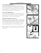
OPERATION CUTTING TECHNIQUES Begin with a large roughing gouge. Place the tool on the tool rest with the heel of the tool on the surface to be cut. Slowly and gently raise the tool handle until the cutting edge comes into contact with the workpiece. Beginning about 2 inches from the tailstock end of the workpiece, roll the flute of the tool (the hollowed-out portion) in the direction of the cut. Make long sweeping cuts in a continuous motion to turn the piece to a cylinder (Fig. T).
OPERATIONS Fig. T Fig. V Fig. U Fig. W MOUNTING ON THE FACE PLATE Use of the face plate is the most common for holding a block of wood for turning bowls and plates. This is an alternative option for workpieces with diameters that are greater than the 12-inch throat of the lathe. To mount the stock to the face plate, select a stock that is at least .2 inches (5 mm) larger than each dimension of the finished workpiece.
OPERATION TO SHAPE THE OUTSIDE OF THE BOWL (FIG. W) Odd shaped burls, crotches and other irregular shaped blanks require special preparation before mounting in a chuck or onto a face plate. Remove the bark, if there is any from what appears to be the center of the top of the workpiece. Drive the spur center into the top of the workpiece with a mallet or a dead blow hammer. Slip the spur center into the headstock taper and bring the tailstock with a live center into position.
MAINTENANCE Keep your machine clean. At the end of each day, clean the machine. Wood contains moisture, meaning that sawdust and wood chips can cause rust if not removed. Regular oil attracts dust and dirt. Teflon lubricant tends to dry and has less of a tendency to accumulate dirt and saw dust. Periodically check that all nuts and bolts are tight. The drive belt should last for many years depending on usage, but it needs to be inspected regularly for cracks, cuts and general wear.
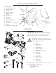
EXPLODED VIEW & PARTS LIST
EXPLODED VIEW & PARTS LIST No PART NUMBER 1 2 3 4 5 6 7 8 9 10 11 12 13 14 15 16 17 18 19 20 21 22 23 24 25 26 27 28 29 30 31 32 33 34 35 36 37 38 39 40 41 42 43 44 45 46 47 48 49 50 51 52 53 54 55 56 57 3427-001 3427-002 3427-003 3427-004 3427-005 3427-006 3427-007 3427-008 3427-009 3427-010 3427-011 3427-012 3427-013 3427-014 3427-015 3427-016 3427-017 3427-018 3427-019 3427-020 3427-021 3427-022 3427-023 3427-024 3427-025 3427-026 3427-027 3427-028 3427-029 3427-030 3427-031 3427-032 3427-033 3427-034
LIMITED TWO YEAR WARRANTY WEN Products is committed to build tools that are dependable for years. Our warranties are consistent with this commitment and our dedication to quality. LIMITED WARRANTY OF WEN CONSUMER POWER TOOLS PRODUCTS FOR HOME USE GREAT LAKES TECHNOLOGIES, LLC (“Seller”) warrants to the original purchaser only, that all WEN consumer power tools will be free from defects in material or workmanship for a period of two (2) years from date of purchase.