
Use and Care Manual
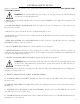
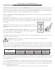
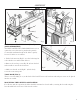

Disengaged
Position
Locked
Position
Fig. O
10
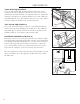
ADJUSTMENTS
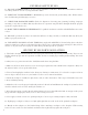
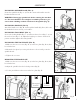
TOOL REST ADJUSTMENTS
Users can adjust the height, position and angle of the tool rest as-
sembly. Loosen the locking lever (Fig. M - 1) on the tool rest base to
slide the base forward and back or to adjust the angle of it. Tighten the
locking lever firmly before operating the lathe. Loosen the small lock-
ing handle (Fig. M - 2) to raise and lower the tool rest or to also adjust
its angle. Tighten the handle before operating the lathe.
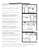
TAIL STOCK ADJUSTMENTS
Loosen the tail stock locking lever (Fig. N - 3) and slide the tailstock
into the desired position. Retighten the locking lever. The quill lock-
ing handle (Fig. N - 2) locks and unlocks the tail stock quill. Use the
handwheel (Fig. N - 1) to advance and retract the quill.
1
2
Fig. M
INDEXING/SPINDLE LOCK (FIG. O)
Indexing is used to create evenly spaced features in a workpiece while
keeping the lathe and spindle locked. For example, when cutting flutes
on a spindle blank with a handheld router, you may want evenly space
features and designs placed around the circumference of the work-
piece. The 24 index positions are marked around the center spur to
help rotate the workpiece evenly for accurately spaced features.
Place the spindle lock in the locked position to help maintain a certain
index point. Make sure to disengage the spindle lock before starting
the lathe again.
Fig. N
1
2
3