
Use and Care Manual

7
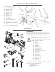
ASSEMBLY
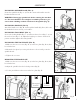
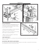
INSTALLING SPINDLE LOCK (FIG. A)
Locate the spindle lock (Fig. A - 1) from the carton and install it onto the
headstock with a wrench.
WARNING: Disengage spindle lock before turning the machine
on. The lock should be in it’s highest available position to pre-
vent it from colliding with the rotation of the spindle (Fig. E).
INSTALLING HANDLE (FIG. B)
Attach the handle screw (Fig. B - 2) through the handle (Fig. B - 1) hole onto
the handwheel. Secure it using a screwdriver.
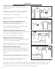
INSTALLING TOOL REST (FIG. C)
Loosen the locking handle (Fig. C - 3) and insert the tool rest (Fig. C - 1) into
the tool rest base (Fig. C - 2). Adjust the height up or down to the desired
position and then tighten the locking handle.
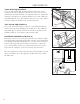
INSTALLING THE FACE PLATE (FIG. D)
1. Make sure the two set screws (Fig. D - 1) in the face plate (Fig. D - 2) have
been backed out.
2. Mount the face plate by screwing it clockwise as far as it will go onto the
spindle threads.
3. Tighten the set screws.
REMOVING THE FACE PLATE
1. Make sure the two set screws (Fig. D - 1) in the face plate (Fig. D - 2) have
been backed out.
2. Adjust the spindle lock to the locked position (Fig. E).
3. Use the provided wrench to unscrew the face plate (Fig. F).
1
Fig. A
Fig. B
Fig. C
1
2
1
2
3
1
2
Fig. D
Disengaged
Position
Locked
Position
Fig. E
Fig. F