
Assembly Guide


CROSS SIDE ASSEMBLY
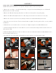
NOTE: The numbers listed below correspond to the figure numbers shown in the pictures.
1. Remove the screw (Fig. 1 - 1) and lock washer (Fig. 1 - 2) (parts 52 and 192) holding the cross slide handle
(86A) onto the cross slide screw (89).
2. Remove the dial (87) and spring (190) from cross slide screw. It may take some gentle prying.
3. Remove the dial bracket (88) from the cross slide using a hex wrench. Unscrew the two screws (116).
4. Remove the current cross feed screw by turning it clockwise (it is left-hand threaded). Set it aside.
5. Insert the new cross feed screw. Turn it counterclockwise to tighten. Note the position of the set screw; it will be
needed later.
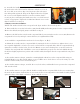
6. Mount the new cross bracket on the cross feed screw. Tighten using the two included M4x12 screws.
7. Check the digital readout box to ensure that the set screw is retracted far enough to allow insertion of the cross
slide transition shaft.
8. Mount the digital readout box on the cross slide screw. Secure to the bracket with two included M3x25 screws,
but do not tighten all the way yet.
9. Assemble the screw, lock washer, and handle from earlier onto the cross slide transition shaft.
Fig. 1
2
1
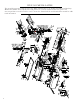
ASSEMBLY
Fig. 9
Fig. 8
Fig. 7
Fig. 6Fig. 5Fig. 4
Fig. 3
Fig. 2
2