Table of Contents Technical data…………………………………………………………… 2 General safety rules……………………………………………………… 3 Additional safety rules…………………………………………………... 5 Electrical requirements………………………………………………..…. 8 Know your table saw……………………………………………………. 10 Unpacking……………………………………………………………….. 11 Assembly and adjustments……………………………………………… 12 Operation………………………………………………………………... 20 Maintenance…………………………………………………………….. 24 Trouble shooting………………………………………………………… 25 Exploded view…………………………………………………………..
General Safety Rules The purpose of safety symbols is to attract your attention to possible dangers. The safety symbols, and the explanations with them, deserve your careful attention and understanding. The safety warnings do not by themselves eliminate any danger. The instructions or warnings they give are not substitutes for proper accident prevention measures. Symbol Meaning Safety Alert Symbol: Indicated danger, warning, or caution, may be used in conjunction with other symbols or pictographs.
NEVER STAND ON TOOL OR ITS STAND Serious injury could occur if the tool is tipped or if the cutting tool is accidentally contacted. Do not store materials on or near the tool such that it is necessary to stand on the tool or its stand to reach them. CHECK DAMAGED PARTS Before further use of the tool, a guard or other part that is damaged should be carefully checked to ensure that it will operate properly and perform its intended function.
Additional Safety Rules Tool Care DO NOT ALTER OR MISUSE TOOL These tools are precision built. Any alteration or modification not specified is misuse and may result in dangerous conditions. AVOID GASEOUS AREAS Do not operate electric tools in gaseous or explosive at mospheres. Motors in these tools normally spark, and may result in a dangerous condition. MAINTAIN TOOLS WITH CARE Keep tools sharp and clean for better and safer performance. Follow instructions for lubricating and changing accessories.
d. NOT ripping workpiece that is twisted or warped or does not have a straight edge to guide along the rip fence. e. NOT releasing work until you have pushed it all the way past the saw blade. f. Using a Push Stick for ripping widths of 2" to 6" and an auxiliary fence and Push Block for ripping widths narrower than 2" (See ―Basic Saw Operation, Using the Rip Fence ―section.). g. NOT confining the cut-off piece when ripping or cross -cutting. h.
spreader is in proper alignment with the saw blade. If ripping at the time, check to see if rip fence is parallel with the saw blade. Readjust as indicated. g. NEVER gang crosscut — lining up more than one workpiece in front of the blade (stacked vertically or horizontally outward on the table) and then pushing thru saw blade. The blade could pick up one or more pieces and cause a binding or loss of control and possible injury. h.
Electrical Requirements Double Insulated Tools Double Insulation is a design concept used in electric power tools which eliminates the need for the three wire grounded power cord and grounded power supply system. It is a recognized and approved system by Underwriter’s Laboratories, CSA and Federal OSHA authorities. IMPORTANT: Servicing of a tool with double insulation requires care and knowledge of the system and should be performed only by a qualified service technician.
IMPROPER CONNECTION of the equipment grounding conductor can result in electric shock. The conductor with the green insulation (with or without yellow stripes) is the equipment grounding conductor. If repair or replacement of the electric cord or plug is necessary, DO NOT connect the equipment grounding conductor to a live terminal. CHECK with a licensed electrician or service personnel if you do not completely understand the grounding instructions, or if you are not sure if the tool is properly grounded.
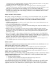
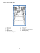
Know Your Table Saw A B C D E F Miter Gauge Blade Guard Table Rip Fence Scale Rip Fence Storage Blade Bevel Locking Lever G H I J K 10 Hand Wheel Leg Stand ON/OFF Switch with Safety Key Blade Bevel Scale Miter Gauge Storage
Unpacking WARNING - to prevent accidental starting that could cause possible serious personal injury; assemble all parts to your saw before connecting it to power supply. Saw should never be connected to power supply when you are assembling parts, making adjustments, installing or removing blades, or when not in use. WARNING - if any parts are missing, do not operate this tool until the missing parts are replaced. Failure to do so could result in possible serious personal injury.
Assembly and Adjustments WARNING! Prior to performing any assembly procedures, make sure the 10" table saw is disconnected from its electrical power source. Assembling the Leg Stand (Figure 1) Warning: The stamped rails may have sharp edges. Be careful in handling the rails to prevent being cut. NOTE: Use the screws, washers, and lock nuts supplied in the hardware bag to attach the pieces of the leg stand together. Do not tighten the hardware completely until the leg stand is completely assembled. 1.
Mounting Table Saw to Workbench (Figure 3 & 4) If table saw is to be used in a permanent location, it should be fastened securely to a firm supporting surface such as a stand or workbench, using the four mounting holes, 1 (Figure 3) two of which are shown.
Mounting to Plywood (Figure 5) An alternative method of securing your table saw is to fasten the saw base to a mounting board 24" x 24" minimum size to prevent saw from tipping while in use. Any good grade of plywood with a 3/4" minimum thickness is recommended. 1. Follow instructions for mounting to workbench, substituting a plywood board 24" x 24" minimum size and using 5/16" flat head machine screws, flat washers, and hex nuts (not included).
90° and 45° Positive Stops Adjustment (Figure 6, 7 & 8) Warning: To prevent personal injury, always disconnect the plug from power source before making any adjustments. The saw has positive stops that will quickly position the saw blade at 90° or 45° to the table. Make the following adjustments only if necessary. NOTE: 90° and 45° blade adjustment screws require a 5 mm Allen wrench (not supplied) and a 10 mm wrench or socket (not supplied) for adjustment.
Blade Parallel to Miter Gauge Groove Adjustment (Figure 9, 10 & 11) Warning: To prevent personal injury, always disconnect the plug from power source before making any adjustments. Warning: If the blade is misaligned by more than 1/8", do not attempt to align or operate the saw. Have a qualified service technician perform blade alignment. 1. Move the blade guard out of the way. 2. Raise the blade to the maximum height by turning the hand wheel (1, Figure 9) counterclockwise.
16. Stand the saw on its left side and tighten the four center adjustment nuts (7, Figure 11). 17. Place the saw upright and re-check the alignment to make sure the blade is parallel to the miter slot. Removal and Installation of the Blade (Figure 12, 13 & 14) Warning: Disconnect plug from power source before performing any assembly, adjustment or repair to avoid possible injury. NOTE: Clean blade of any excess oil before installation. 1. Remove the table insert (1, Figure 12). 2.
Installing the blade guard system Warning: To prevent personal injury, always disconnect plug from power source before installing or removing the blade guard. POSITIONING THE RIVING KNIFE (Figure 15 & 16) 1. Remove table insert using finger hole. 2. Raise the blade as high as it will go and set it perpendicular to table (0° on bevel scale) (Figure 15). 3. Rotate the riving knife release lever clockwise, so that it points upward (Figure 15). 4.
Installing the anti-kickback device (Figure 18) While pulling out the attachment pin, attach the Anti-Kickback Device into the flat recessed area A of the riving knife (Figure 18). Slide the Anti-Kickback Device down until it drops into the recessed area – then release the attachment pin such that the Anti-Kickback Device locks onto the riving knife immediately behind the guard assembly. Check that the attachment pin is securely connected into locking hole.
Operation Warning: For your own safety, always observe the following safety precautions. • • • • • • • • • • • • • • Never make these cuts freehand (without using the miter gauge or other auxiliary devices) because the blade could bind in the cut and cause a KICKBACK or cause your fingers or hand to slip into the blade. Always tighten the miter gauge handle securely when in use. Remove rip fence from table during any operations which utilize the miter gauge.
safety key removed, the switch will not operate. NOTE: If the safety key is removed while the saw is running, the saw can be turned OFF, but cannot be restarted without inserting the safety key. Overload Reset Switch (Figure 19) To prevent accidental startup if the overload reset switch is pushed, the ON/OFF switch should be in the OFF position, and the plug should be removed from the power source while cool down takes place. Overheating may be caused by misaligned parts or a dull blade.
Repetitive Cutting (Figure 21) REPETITIVE CUTTING is known as cutting a quantity of pieces the same length without having to mark each piece (Figure 21). When making repetitive cuts from a long work piece, make sure it is supported. Warning: Never use the rip fence as a length stop because the cutoff piece could bind between the fence and the blade causing a kickback. When making repetitive cuts, clamp a block of wood 3" long to the table at desired length to act as a length stop.
Bevel Crosscutting (Figure 23) BEVEL CROSSCUTTING is the same as crosscutting except that the wood is also cut at an angle … other than 90° with the flat side of the wood (Figure 23). Adjust the blade to the desired angle and lock it. Use the Miter Gauge in the groove to the RIGHT of the blade. It cannot be used in the groove to the LEFT because the blade guard will interfere. Hold the workpiece with your right hand and the lock knob with your left hand.
Maintenance For your own safety, turn switch ―OFF‖ and remove plug from power source outlet before maintaining or lubricating your saw. Do not allow sawdust to accumulate inside the saw. Frequently blow out any dust that may accumulate inside the saw cabinet and the motor. Clean your cutting tools with a Gum and Pitch Remover. The cord and the tool should be wiped with a dry clean cloth to prevent deterioration from oil and grease. Warning: Certain cleaning agents and solvents can damage plastic parts.
Trouble shooting WARNING: To avoid injury from an accidental start, turn the power switch off, remove the safety key and remove the plug from the power source before making any adjustment. PROBLEM Saw will not start. CAUSE 1. Saw not plugged in. 2. Fuse blown or circuit breaker tripped. 3. Cord damaged. Does not make accurate 45° and 90° rip cuts. 1. Positive stop not adjusted correctly. 2. Tilt angle pointer not set correctly. Material pinches blade when ripping. Material binds on splitter.
Exploded View 26
Parts List Item # 1 2 3 4 5 6 7 8 9 10 11 12 13 14 15 16 17 18 19 20 21 22 23 24 25 26 27 28 29 30 31 32 33 34 35 36 37 38 39 40 Stock # 3710-001 3710-002 3710-003 3710-004 3710-005 3710-006 3710-007 3710-008 3710-009 3710-010 3710-011 3710-012 3710-013 3710-014 3710-015 3710-016 3710-017 3710-018 3710-019 3710-020 3710-021 3710-022 3710-023 3710-024 3710-025 3710-026 3710-027 3710-028 3710-029 3710-030 3710-031 3710-032 3710-033 3710-034 3710-035 3710-036 3710-037 3710-038 3710-039 3710-040 Description N
Item # 81 82 83 84 85 86 87 88 89 90 91 92 93 94 95 96 97 98 99 100 101 102 103 104 105 106 107 108 109 110 111 112 113 114 115 116 117 118 119 120 Stock # 3710-081 3710-082 3710-083 3710-084 3710-085 3710-086 3710-087 3710-088 3710-089 3710-090 3710-091 3710-092 3710-093 3710-094 3710-095 3710-096 3710-097 3710-098 3710-099 3710-100 3710-101 3710-102 3710-103 3710-104 3710-105 3710-106 3710-107 3710-108 3710-109 3710-110 3710-111 3710-112 3710-113 3710-114 3710-115 3710-116 3710-117 3710-118 3710-119 3710
Item # 164 165 166 168 169 170 171 172 173 174 175 176 177 178 179 180 181 182 183 184 185 186 187 188 189 190 191 192 193 194 195 196 197 198 199 200 201 202 203 204 Stock # 3710-164 3710-165 3710-166 3710-168 3710-169 3710-170 3710-171 3710-172 3710-173 3710-174 3710-175 3710-176 3710-177 3710-178 3710-179 3710-180 3710-181 3710-182 3710-183 3710-184 3710-185 3710-186 3710-187 3710-188 3710-189 3710-190 3710-191 3710-192 3710-193 3710-194 3710-195 3710-196 3710-197 3710-198 3710-199 3710-200 3710-201 371
Limited Two Years Warranty WEN Products is committed to build tools that are dependable for years. Our warranties are consistent with this commitment and our dedication to quality. LIMITED WARRANTY OF WEN CONSUMER POWER TOOLS PRODUCTS FOR HOME USE GREAT LAKES TECHNOLOGIES, LLC ("Seller") warrants to the original purchaser only, that all WEN consumer power tools will be free from defects in material or workmanship for a period of two (2) years from date of purchase.