OPERATOR’S MANUAL 14" Band Saw Model # 3914
Table of Contents Technical data ..................................................................................................................................2 General safety rules..........................................................................................................................4 Specific safety rules for band saws ..................................................................................................6 Electrical information ............................................
General safety rules Safety is a combination of common sense, staying alert and knowing how your band saw works. SAVE THESE SAFETY INSTRUCTIONS. WARNING: To avoid mistakes that could cause serious injury, do not plug in the band saw until the following steps have been read and understood. 1. READ and become familiar with this entire instruction manual. LEARN the tool’s applications, limitations, and possible hazards. 2. AVOID DANGEROUS CONDITIONS.
13. NEVER LEAVE A RUNNING TOOL UNATTENDED. Turn the power switch to OFF. Do not leave the tool until it has come to a complete stop. 14. NEVER STAND ON A TOOL. Serious injury could result if the tool tips or is accidentally hit. DO NOT store anything above or near the tool. 15. DO NOT OVERREACH. Keep proper footing and balance at all times. Wear oilresistantrubber-soled footwear. Keep the floor clear of oil, scrap, and other debris. 16. MAINTAIN TOOLS PROPERLY.
Specific safety rules for band saws 1. To avoid injury from unexpected movement, make sure the saw is on a firm, level surfaceand secured properly to prevent rocking. Make sure there is adequate space for operations. Bolt the saw to a support surface to prevent slipping or sliding during operation. 2. Turn off and unplug the saw before moving it. 3. Use the correct size and style of blade. 4. Make sure the blade teeth point down and toward the table. 5.
16. Don’t leave the work area until all moving parts have stopped. Shut off the power to master switches. Remove the switch key from the band saw and store it in a safe place away from children. Childproof the workshop! Electrical information Grounding Instructions IN THE EVENT OF A MALFUNCTION OR BREAKDOWN, grounding provides the path of least resistance for electric current and reduces the risk of electric shock.
Guidelines for Using Extension Cords Make sure your extension cord is in good condition. When using an extension cord, be sure to use one heavy enough to carry the current your product will draw. An undersized cord will cause a drop in line voltage resulting in loss of power and overheating. The table below shows the correct size to be used according to cord length and nameplate ampere rating. When in doubt, use a smaller-numbered gauge (the smaller the gauge number, the heavier the cord).
Know your band saw 2 1 2 3 4 5 6 7 8 1 3 7 4 8 5 6 9 Switch Blade-tension-adjusting knob Blade Work table Blade tension wheel Storage Rip fence Miter gauge
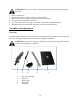
WARNING: For your own safety, read the instruction manual before operating the band saw. 1. 2. 3. 4. 5. 6. Wear eye protection. Do not wear gloves, neckties, jewelry, or loose clothing. Make sure the saw is properly secured on a firm, level surface. Use only the recommended accessories. Use extra caution with very large, very small, or awkwardly shapedworkpieces. Keep hands away from the blade at all times to prevent accidental injury.
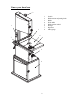
6 7 10 6 7 8 9 10 11 12 8 11 9 12 Base Left panel Right panel Door assembly Rear panel Brace (2) Shelf Parts bag includes: Handwheel Assembly (1), WingKnob Screw (4), M6 x 16 Hex Head Bolt (4), M6 FlatWasher (4), Push Stick Hook w/nut (1), Hex Wrench (1)and Open End Wrench (1). Hardware bag includes: M8 Flat Washer (4), M6 x 16Hex Head Bolt (12), M6 x 16 Socket Head Bolt (4), M6 x40 Flat Head Screw (4), M6 Flat Washer (24), M6 HexNut (8), M5 x 6 Pan Head Screw (2) and M5 FlatWasher (2).
Assembly CAUTION: Do not attempt assembly if parts are missing.Use this manual to order replacement parts. WARNING: To avoid injury, do not attempt to run oruse this machine until all parts are assembled and workingproperly. Assembly stand Note: Hand-tighten all hardware during assembly. Do notcompletely tighten hardware until assembly is complete. Refer to Exploded View and Parts List, Page 26. 1. Place base (Item 6) on flat surface.
Centering the table 1. Loosen the hex bolts mounting the trunnion to the saw frame (see Figure 1). 2. Move the table sideways as required, until the saw blade runs through the center of the table insert. 3. Re-tighten hex bolts for trunnion and recheck the saw blade position. Setting table square to saw blade Refer to Figures 1 and 2. Loosen the handle on the table trunnion and place asuitably sized square against the saw blade. If the tablerequires adjustment, proceed as follows: 1.
Figure 5 Attach pushstick p sto orage hook Hook Refer to Figure F 5. 1. Threaad hex nut co ompletely upp to unthreadded portion of hoook. 2. Threaad the hook into the saw w’s frame sevveral turns. 3. Tightten hex nut against a saw frame. f 4. Storee pushstick on o hook whenn not in use.. Pushstick Attach drive d belt ten nsion handw wheel Refer to figure 6. 1. Placee handwheel assembly onnto shaft. 2. Securre in position n with setscrrew.
Changing and adjusting the saw blade This band saw is factory-equipped with a general-purpose,woodcutting blade; the saw blade is set prior to delivery. To change the saw blade, follow the procedure below: WARNING: To avoid injury from unexpected starting,whenever changing the saw blade or carrying outadjustments, switch the band saw off and remove thepower cord from the main outlet. To avoid injury tohands when handling the saw blade, wear gloveswhenever necessary. Blade Figure 7 1.
Setting the cutting height 1. The upper blade guide should be set as close as is practically necessary against the workpiece. 2. To adjust this height, loosen the locking knob in the center of the adjusting knob (See Figure 8). 3. Set the blade guide to the required height by turning the guidepost-adjusting knob. 4. Tighten locking knob after setting. GuidepostAdjusting Knob Locking Knob Figure 8 Adjusting the blade guides NOTE: Upper and lower blade guides are adjusted inthe same manner.
Adjusting the rip fence Fence Body The locking pressure of the rip fence has been factory-set. Figure 12 The fence handle has a cam action, press down thehandle to clamp tightly to the table after setting ripfence to desired position. Fence Extrusion NOTE: The rip fence can be used on both sides of theblade. The rip fence extrusion needs to be positioned onthe side of the fence body that is closest to the blade.
BLADE SELECTION 1. Blades vary depending on type of material, size of workpiece and type of cut that is being performed. 2. Characteristics which make blades different are width, thickness and pitch. BLADE WIDTH 1. Width of blade describes distance from tip of a tooth to back of blade. 2. Width of blade affects rigidity of blade. A wider blade wanders less and produces a straighter cut. 3. Width of blade also limits the smallest radius which can be cut. A 1⁄4″ wide blade can cut about a 1⁄2″ radius.
CONTOUR SAWING 1. When contour sawing, use both hands to keep workpiece flat against table and guided along desired path. 2. Avoid positioning hands in line with the blade. If hands slip, they may contact blade. 3. Try to stand in front of the saw. Place hands over the portion of the table to the right of the blade before cutting. 4. Cut small corners by sawing around them. Saw to remove scrap until desired shape is obtained. BEVEL CUTTING 1. 2. 3. 4.
Operation ON/OFF Switch(Figure 14) 1. To turn the saw ON, move the switch to the up (ON) position. 2. To turn the saw OFF, move the switch to the down (OFF) position. 3. To lock the switch in the OFF position: Figure 14 a) Wait until the band saw has come to a complete stop. b) Remove the switch key from the switch housing. Store the switch key in a safe place. 4. To unlock the switch and turn the saw ON, insert the switch key into the switch, and move the switch to the ON position.
Cutting Curves When cutting curves, carefully turn the work piece so the blade follows without twisting. If the curve is so sharp that you repeatedly back up and cut new kerf, use either a narrower blade or a blade with more set (teeth further apart). When a blade has more set, the work piece turns easier with a rougher cut. When changing a cut, do not withdraw the work piece from the blade. The blade may get drawn off the wheels.
Exploded view and parts list 22
Item # 1 2 3 4 5 6 7 8 9 10 11 12 13 14 15 16 17 18 19 20 21 22 23 24 25 26 27 Stock # 3914-101 3914-102 3914-103 3914-104 3914-105 3914-106 3914-107 3914-108 3914-109 3914-110 3914-111 3914-112 3914-113 3914-114 3914-115 3914-116 3914-117 3914-118 3914-119 3914-120 3914-121 3914-122 3914-123 3914-124 3914-125 3914-126 3914-127 Description Lower Door Assembly Upper Door Assembly Retaining Ring Upper Wheel Shaft Tension Block Flange Nut Guide Plate Nut Spring Shaft Retaining Ring Tension Bracket Frame Push
Item # 1 2 3 4 5 6 7 8 9 10 11 12 13 14 15 16 17 18 19 20 21 22 23 24 25 26 27 28 29 30 31 32 33 Stock # 3914-201 3914-202 3914-203 3914-204 3914-205 3914-206 3914-207 3914-208 3914-209 3914-210 3914-211 3914-212 3914-213 3914-214 3914-215 3914-216 3914-217 3914-218 3914-219 3914-220 3914-221 3914-222 3914-223 3914-224 3914-225 3914-226 3914-227 3914-228 3914-229 3914-230 3914-231 3914-232 3914-233 Description Tap Screw Plate Rack Guide Post Pressure Plate Pin Rack Gear and Shaft Guide Block Pin Guide Car
Item # 1 2 3 4 5 6 7 Stock # 3914-301 3914-302 3914-303 3914-304 3914-305 3914-306 3914-307 Description Left Panel Brace Rear Panel Shelf Right Panel Base Door Assembly Item # 8 9 10 11 12 13 14 Stock # 3914-308 3914-309 3914-310 3914-311 3914-312 3914-313 3914-314 26 Description Screw Flat Washer Flat Washer Bolt Screw Nut Bolt
Limited two years warranty WEN Products is committed to build tools that are dependable for years. Our warranties are consistent with this commitment and our dedication to quality. LIMITED WARRANTY OF WEN CONSUMER POWER TOOLS PRODUCTS FOR HOME USE GREAT LAKES TECHNOLOGIES, LLC ("Seller") warrants to the original purchaser only, that all WEN consumer power tools will be free from defects in material or workmanship for a period of two (2) years from date of purchase.