4-INCH BANDSAW WITH STAND Model # 3966 bit.ly/wenvideo IMPORTANT: Your new tool has been engineered and manufactured to WEN’s highest standards for dependability, ease of operation, and operator safety. When properly cared for, this product will supply you years of rugged, trouble-free performance. Pay close attention to the rules for safe operation, warnings, and cautions. If you use your tool properly and for intended purpose, you will enjoy years of safe, reliable service.
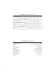
TABLE OF CONTENTS 2 3 4 5 7 8 14 15 18 21 Technical Data General Safety Rules Specific Safety Rules For Band Saw Electrical Information Know Your Band Saw Assembly and Adjustments Maintenance Operation Exploded View & Parts List Warranty TECHNICAL DATA Model Number: Motor: Throat: Cutting Depth: Speeds: Table Angle: Working Table: Blade Length: Blade Width: Weight: 2 3966 120 V, 60 Hz, 1100W, 9.5A 13-3/8 inches 8.85 inches 1480/3280 FPM 0 to 45 degrees 21.45 x 15.
GENERAL SAFETY RULES Safety is a combination of common sense, staying alert and knowing how your item works. SAVE THESE SAFETY INSTRUCTIONS. WARNING: To avoid mistakes and serious injury, do not plug in your tool until the following steps have been read and understood. 1. READ and become familiar with this entire instruction manual. LEARN the tool’s applications, limitations, and possible hazards. 2. AVOID DANGEROUS CONDITIONS. Do not use power tools in wet or damp areas or expose them to rain.
GENERAL SAFETY RULES 15. DO NOT OVERREACH. Keep proper footing and balance at all times. Wear oil-resistant rubber-soled footwear. Keep the floor clear of oil, scrap, and other debris. 16. MAINTAIN TOOLS PROPERLY. ALWAYS keep tools clean and in good working order. Follow instructions for lubricating and changing accessories. 17. CHECK FOR DAMAGED PARTS. Check for alignment of moving parts, jamming, breakage, improper mounting, or any other conditions that may affect the tool’s operation.
SPECIFIC RULES FOR BAND SAW 11. Small pieces should be secured with clamps or fixtures. Do not hold small pieces with your hand because your fingers might go under the blade guard. 12. Support round work properly (use a V block or press it against the miter gauge) to prevent it from rolling and the blade from biting. 13. Cut only one workpiece at a time. Make sure the table is clear of everything except the workpiece and its guides before you turn the saw on. 14. Always WATCH the saw run before each use.
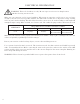
ELECTRICAL INFORMATION WARNING: This tool is for indoor use only. Do not expose to rain or use in damp locations. Guidelines for using extension cords Make sure your extension cord is in good condition. When using an extension cord, be sure to use one heavy enough to carry the current your product will draw. An undersized cord will cause a drop in line voltage resulting in loss of power and overheating. The table below shows the correct size to be used according to cord length and nameplate ampere rating.
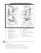
KNOW YOUR BAND SAW J F A G O H B I C P M D T E Q N R L K S A B C D E F G H I J K Tension Knob Light ON/OFF Switch Machine ON/OFF Switch Locking Fence Fence Lock Upper Housing Knob Blade Guard Adjustment Knob Blade Guard Blade Bearings Adjustment Knobs Tension Release Lever Miter Gauge L M N O P Q R S T Lower Housing Knob Table Bevel Lock Dust Port Blade Tracking Adjusting Knob Lower Spindle Tracking Adjustment Capacitor Box Motor Dust Collection Drawer Belt Tension Adjustment Knob W
ASSEMBLY UNPACKING Carefully unpack the band saw and all its parts, and compare against the list below. Do not discard the carton or any packaging until the band saw is completely assembled. WARNING: If any part is missing or damaged, do not plug in the band saw until the missing or damaged part is replaced. 1 3 2 4 5 6 8 7 9 1. Band Saw (1) 2. Guide Rail (1) 3. Table with Insert (1) 4. Rip fence (1) 5. Short Brace (2) 6. Leg (4) 7. Long Brace (2) 8.
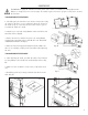
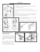
ASSEMBLY WARNING: Unplug the machine from the power source before assembling or making adjustments. Failure to comply may cause serious injury. Assembly requires at least two people to safely move around the bandsaw. TO ASSEMBLE THE STAND 1. Carefully place the band saw on its back as shown above (Fig. A), either on the floor or on a workbench. Prop the bottom of the band saw up on a wooden block in order to have space to assembly the band saw’s stand. Fig. A 2.
ASSEMBLY INSTALLING THE ACCESSORY TOOLS Fig. F 2 1 1. Install the accessory tools assembly to the frame by using M4x10 socket heat bolts (Fig. F - 1). 2. Secure the hook with a hex nut to the frame (Fig. F - 2). 3. Set the rip fence onto the table. Lock it in place with the Fence Lock (Fig. G - 1). NOTE: To reverse the rip fence, remove the fence from the rip fence by loosening the four bolts holding it to the rip fence, reversing the fence, and reattaching the bolts. (Fig. H) 4.
ADJUSTMENTS WARNING: Always be sure that the tool is switched off and unplugged before making any adjustments. TILTING THE TABLE 3 1. Find and loosen the table bevel lock located in back under the saw table (Fig. G - 1). 2. Adjust the table to the desired angle using the table tilting knob (Fig. G - 2) and the angle indicator (Fig. G - 3). 3.
ADJUSTMENTS ADJUSTING BLADE TENSION WARNING: If the tension in the blade is too high, it runs the risk of breaking. If the tension is too low, there is a risk of the blade slipping and stopping during a cut. 1 2 1. Raise the upper blade guide fully using the saw blade tension knob located on the top of the machine (Fig. N - 1). Take the blade width into consideration during the adjustment. 2.
ADJUSTMENTS 1 2 3 Fig. P Fig. Q Fig. R LOWER BLADE GUIDE ADJUSTMENT Fig. S 2 WARNING: The lower blade guide must be adjusted after every blade change and tracking adjustment. 1. Loosen the set screw (Fig. S - 3) and move the entire lower blade guide. Adjsut the guide bearing to a position of 1 to 2 mm from the bottom of the blade. Retighten the set screw (Fig. S - 3). 1 2. Loosen the socket head bolt (Fig. S - 1) and adjust the thrust bearing a position of .5 mm from the rear of the blade.
ADJUSTMENTS CHANGING THE BAND SAW BLADE WARNING: The saw blade is dangerous. Be sure to wear gloves when handling the saw blade in any situation. 1. Loosen the four lock knobs for the guide rail. Remove the guard rail by loosening the four lock knobs located underneath (Fig. W - 1). 2. Open the upper cover and the lower cover. Set the upper blade guide to its lowest position. 3. Loosen the quick release lever until the bandsaw blade has sufficient enough slack. 4. Remove the bandsaw blade from the machine.
OPERATION SUGGESTIONS AND WARNINGS • Do not touch the saw blade when cutting. • During saw operation, wear safety glasses but do not wear gloves. • Cut only one workpiece at a time. • Always hold the workpiece down on the table. • Do not jam any workpieces. • Do not try to slow the blade down by pushing the work piece against the saw blade from the side. • When straight cutting against the fence, use a push stick.
OPERATION USING THE MITER GAUGE 1. Place the miter gauge into the slot on the table. (Fig. BB) 2. Loosen the knob on the gauge to set a new miter angle (between 0 and 60 degrees). 3. Tighten the knob firmly before cutting begins. USING THE PUSH STICK (Fig. CC - DD) The push stick serves as an extension of the hand and protects against accidental contact with the saw blade. The push stick must be used if the distance betwen the bandsaw blade and the rip fence is less than 5.9 inches.
OPERATION Fig. EE CONNECT A DUST COLLECTOR Fig. FF The band saw provides a dust port for collecting various size hoses. It should be connected with a dust collector during any sawing operations. Excess debris gets collected into the dust drawer underneath which should be routinely cleaned out. Dust port sizes include 1-3/4 inches, 2-3/4 inches, and 3-3/4 inches. CUTTING CURVES WITH THE CIRCLE CUTTING GUIDE To make a circular cut, use as narrow of a saw blade as is necessary for the radius of the circle.
EXPLODED VIEW & PARTS LIST
EXPLODED VIEW & PARTS LIST No. Part Number Description 1 3966-001 Socket head screw 2 3966-002 Flat washer Qty. 1 1 3 4 3966-003 3966-004 Blade tension knob Screw 1 1 5 6 7 3966-005 3966-006 3966-007 Bushing Retaining ring Frame cap 8 9 10 3966-008 3966-009 3966-010 11 12 13 No. Part Number Description 60 3966-060 Flat washer 61 3966-061 Bushing Qty.
EXPLODED VIEW & PARTS LIST No. Part Number Description 118 3966-118 Limiting shaft 20 Qty.
LIMITED TWO YEAR WARRANTY WEN Products is committed to build tools that are dependable for years. Our warranties are consistent with this commitment and our dedication to quality. LIMITED WARRANTY OF WEN CONSUMER POWER TOOLS PRODUCTS FOR HOME USE GREAT LAKES TECHNOLOGIES, LLC (“Seller”) warrants to the original purchaser only, that all WEN consumer power tools will be free from defects in material or workmanship for a period of two (2) years from date of purchase.
THANKS FOR REMEMBERING