5-INCH PORTABLE METAL BAND SAW Model # 3975 bit.ly/wenvideo IMPORTANT: Your new tool has been engineered and manufactured to WEN’s highest standards for dependability, ease of operation, and operator safety. When properly cared for, this product will supply you years of rugged, trouble-free performance. Pay close attention to the rules for safe operation, warnings, and cautions. If you use your tool properly and for intended purpose, you will enjoy years of safe, reliable service.
TABLE OF CONTENTS Technical Data General Safety Rules Specific Safety Rules For Band Saw Electrical Information Know Your Band Saw Assembly Adjustments Operation Maintenance Troubleshooting Exploded View & Parts List Warranty 2 3 4 5 6 6 7 9 10 11 12 14 TECHNICAL DATA Model Number: 3975 Motor: 120 V, 60 Hz, 4.5A, 400W (S6 40%) Saw Blade: 56-1/2 x 1/2 in. Cutting Capacity for Square Material: 5 x 4-7/8 in. (90°) 3-1/8 x 3-15/16 in. (45°) Cutting Capacity for Circular Material: 5 in.
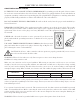
GENERAL SAFETY RULES Safety is a combination of common sense, staying alert and knowing how your item works. SAVE THESE SAFETY INSTRUCTIONS. WARNING: To avoid mistakes and serious injury, do not plug in your tool until the following steps have been read and understood. 1. READ and become familiar with this entire instruction manual. LEARN the tool’s applications, limitations, and possible hazards. 2. AVOID DANGEROUS CONDITIONS. Do not use power tools in wet or damp areas or expose them to rain.
GENERAL SAFETY RULES 15. DO NOT OVERREACH. Keep proper footing and balance at all times. Wear oil-resistant rubber-soled footwear. Keep the floor clear of oil, scrap, and other debris. 16. MAINTAIN TOOLS PROPERLY. ALWAYS keep tools clean and in good working order. Follow instructions for lubricating and changing accessories. 17. CHECK FOR DAMAGED PARTS. Check for alignment of moving parts, jamming, breakage, improper mounting, or any other conditions that may affect the tool’s operation.
ELECTRICAL INFORMATION GROUNDING INSTRUCTIONS IN THE EVENT OF A MALFUNCTION OR BREAKDOWN, grounding provides the path of least resistance for an electric current and reduces the risk of electric shock. This tool is equipped with an electric cord that has an equipment grounding conductor and a grounding plug. The plug MUST be plugged into a matching outlet that is properly installed and grounded in accordance with ALL local codes and ordinances. DO NOT MODIFY THE PLUG PROVIDED.
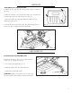
KNOW YOUR BAND SAW B A H I J C G F A B C D E F G H I J Blade Tension Adjustment Knob Run Switch Vise Adjustment Rubber Feet Work Stop Angle Adjustment Lock Locking Pin Variable Speed Adjustment Knob Power Switch Blade Guide Lock E D ASSEMBLY UNPACKING Carefully unpack the band saw and all its parts, and compare against the list below. Do not discard the carton or any packaging until the band saw is completely assembled.
ASSEMBLY ASSEMBLY AND INSTALLATION 1. Attach the four feet (Fig. B - 1) along each respective corner of the base. 2. Place the machine onto a work bench and secure it in place by using the three holes provided in the base (Fig. A). 3. Screw the guide rail to the threaded hole on the vise base. Tighten the nut to fix it. Fig. A 4. Attach the work stop (Fig. B - 2) to the guide rail (Fig. B - 3). Secure it in place by tightening the lock handle. 2 3 1 Fig.
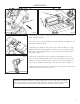
ADJUSTMENTS CUTTING ANGLE ADJUSTMENT This band saw cuts angles anywhere from 0 to 60 degrees. To make an adjustment to the cutting angle: 1 1. Loosen the angle lock handle (Fig. D - 1). 2. Turn the swivel support (Fig. D - 2) until the mark on the support matches the desired angle on the scale. 3. Lock the angle lock handle. 2 SLIDING BLADE GUIDE The sliding blade guide must be adjusted before every cut to a new workpiece. Without the adjustment, the resulting cut could be unclean and jagged. Fig.
OPERATION 1 1 Fig. G Fig. I Fig. H 1. Pull out the pin (Fig. G - 1) from the hole in the saw’s body and tilt the saw to its upper position. 2. Use the vise to secure the workpiece in place (Fig. H - 1). Adjust the cutting speed to the desired rate. 1 3. Push the green button to turn on the power of the saw (Fig. I - 1). The blade will not start running until the run button is also activated. Using the index finger of your right hand, press the run button after turning on the saw’s power (Fig. J - 1).
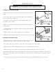
MAINTENANCE WARNING: Turn off the machine and disconnect the power supply before conducting any maintenance work or adjusting any settings. CHANGING THE SAW BLADE 1. Remove the protective casing by unscrewing the six screws shown in Fig. K. 2. Loosen the blade tension by turning the blade tension adjustment knob counterclockwise (Fig. L - 1). 3. Carefully remove the blade, first from the guides and then from around the cast iron pulleys. 4.
TROUBLESHOOTING PROBLEM The motor does not work. Overload circuit tripped CAUSE 1. Defective motor, power cable or plug. 2. Safety cover is open; interlock switch does not work. 1. Motor overload caused by excessive cutting pressure. 2. Motor breakdown. SOLUTION 1. Specialized personnel should check the machine. 2. Close the safety cover. 1. Perform the cut on the piece at the correct pressure. 2. Specialized personnel should check the machine. Inaccurate cut squaring 1. Excessive cutting pressure. 1.
EXPLODED VIEW AND PARTS LIST 12
EXPLODED VIEW AND PARTS LIST No.
LIMITED TWO YEAR WARRANTY WEN Products is committed to build tools that are dependable for years. Our warranties are consistent with this commitment and our dedication to quality. LIMITED WARRANTY OF WEN CONSUMER POWER TOOLS PRODUCTS FOR HOME USE GREAT LAKES TECHNOLOGIES, LLC (“Seller”) warrants to the original purchaser only, that all WEN consumer power tools will be free from defects in material or workmanship for a period of two (2) years from date of purchase.