Table of Contents Technical data………………………………………………………………….. General safety rules…………………………………………………………….. Specific safety rules for drill presses…………………………………………… Electrical information…………………………………………………………... Assembly and adjustments……………………………………………………… Operation………………………………………………………………………... Maintenance…………………………………………………………………….. Exploded view…………………………………………………………………... Parts list………………………………………………………………………….. Warranty………………………………………………………………………….
General safety rules Safety is a combination of common sense, staying alert, and knowing how your drill press works. SAVE THESE SAFETY INSTRUCTIONS. WARNING: To avoid mistakes that could cause serious injury, do not plug in the drill press until the following steps have been read and understood. 1. READ and become familiar with this entire instruction manual. LEARN the tool’s applications, limitations, and possible hazards. 2. AVOID DANGEROUS CONDITIONS.
General safety rules (continued) 13. NEVER LEAVE A RUNNING TOOL UNATTENDED. Turn the power switch to OFF. Do not leave the tool until it has come to a complete stop. 14. NEVER STAND ON A TOOL. Serious injury could result if the tool tips or is accidentally hit. DO NOT store anything above or near the tool. 15. DO NOT OVERREACH. Keep proper footing and balance at all times. Wear oil-resistant rubber-soled footwear. Keep the floor clear of oil, scrap, and other debris. 16. MAINTAIN TOOLS PROPERLY.
Specific safety rules for drill presses WARNING: Do not operate your drill press until it is completely assembled and installed according to the instructions. 1. Never turn on the drill press before clearing the table of all objects (tools, scraps, etc.). 2. Always keep hands and fingers away from the drill bit. 3. Do not drill material that does not have a flat surface, unless a suitable support is used. 4. Never start the drill press with the drill bit pressed against the workpiece. 5.
Electrical information Grounding instructions IN THE EVENT OF A MALFUNCTION OR BREAKDOWN, grounding provides the path of least resistance for electric current and reduces the risk of electric shock. This tool is equipped with an electric cord that has an equipment grounding conductor and a grounding plug. The plug MUST be plugged into a matching outlet that is properly installed and grounded in accordance with ALL local codes and ordinances. DO NOT MODIFY THE PLUG PROVIDED.
Electrical information (continued) WARNING: This drill press is for indoor use only. Do not expose to rain or use in damp locations. Guidelines for using extension cords Make sure your extension cord is in good condition. When using an extension cord, be sure to use one heavy enough to carry the current your product will draw. An undersized cord will cause a drop in line voltage resulting in loss of power and overheating.
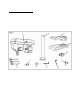
Assembly and adjustments Unpacking (Fig. 2) Unpack the drill press and all its parts, and compare against the list below. Do not discard the carton or any packaging until the drill press is completely assembled. To protect the drill press from moisture, a protective coating has been applied to the machined surfaces. Remove this coating with a soft cloth moistened with kerosene or WD-40®. Do not use acetone, gasoline, or lacquer thinner to clean. Apply a coat of good paste wax to the table and column.
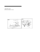
Assembly and adjustments (continued) Tools needed for assembly • Adjustable wrench • Hammer and block of wood Base to column (Fig. 3) 1. Set the base (1) on the floor. 2. Place the column tube (2) on the base (1), align the column support holes with the base holes. 3. Install a bolt (3) in each column support hole and tighten with the wrench. Table to column 1. Slide the table down onto the column, and install the table lock handle. 2.
Assembly and adjustments (continued) Feed handles 1. Thread the three feed handle rods into the holes on the feed hub. 2. Hand tighten. Note: One or two of the feed handles may be removed if an unusually-shaped workpiece interferes with handle rotation. Laser batteries 1. Turn off the laser. 2. Insert 2 "AAA" batteries in the laser battery compartment. 3. Close the laser battery cover. CAUTION: Remove the laser light batteries when the tool is to be stored without use for a few days or more.
Assembly and adjustments (continued) Install the chuck (Fig. 6) 1. Inspect and clean the taper hole in the chuck (1) and the spindle (2). Remove all grease, coatings, and particles from the chuck and spindle surfaces with a clean cloth. 2. Open the chuck jaws (3) by turning the chuck barrel clockwise by hand. Make sure the jaws are completely recessed inside the chuck. 3.
Assembly and adjustments (continued) Install the belt (Fig. 8) 1. Open the pulley and belt cover (1). 2. Loosen the belt tension lock knob (2) and bolts on both sides of the drill press. 3. Slide the motor (3) as close to the drill press head as possible. 4. Place a belt (4) on the motor pulley (5) and the spindle pulley (6) in the proper position for the desired speed (see Fig. 9). 5. Pull the motor away from the drill press head until the belt is properly tensioned.
Assembly and adjustments (continued) WARNING: Disconnect the drill press from the power source before making any speed adjustments. Adjust speeds and tension the belt (Fig. 10) 1. 2. 3. 4. Open the drill press pulley cover (1). Loosen the belt tension knob (2) and bolts on both sides of the drill press head. Pull the motor (3) toward the drill press head. Set the belt on the desired steps of the motor (4) and spindle (5) pulleys according to the belt positions on the spindle speed chart (Fig. 9). 5.
Assembly and adjustments (continued) Tilt the table (Fig. 11) The table can be tilted from 0 to 45° to the left and right. 1. Loosen the bevel lock bolt (1) with a wrench. 2. Tilt the table (2) to the desired angle, using the bevel scale (3) as a basic guide. 3. Re-tighten the bevel lock bolt (1). 4. To return the table to its original position, loosen the bevel lock bolt. Realign the bevel scale (2) to the 0° setting. 5. Tighten the bevel lock bolt (1) with the wrench.
Assembly and adjustments (continued) Square the table to the head (Fig. 12) 1. Insert a 3" (7.6 cm) drill bit (1) into the chuck (2) and tighten. 2. Raise and lock the table (3) about 1" (2.5 cm) from the end of the drill bit. 3. Place a combination square (4) on the table as shown. The drill bit should be parallel to the straight edge of the square. 4. If an adjustment is needed, loosen the bevel lock (5) with a wrench. 5. Square the table to the bit by tilting the table. 6.
Assembly and adjustments (continued) WARNING: DO NOT STARE DIRECTLY AT THE LASER BEAM! A hazard may exist if you deliberately stare into the beam. Please observe all safety rules as follows: The laser shall be used and maintained in accordance with the manufacturer's instructions. Never aim the beam at any person or an object other than the workpiece. Do not project the laser beam into the eyes of others.
Operation Position the table and workpiece (Fig. 15) Always place a piece of backup material (1) (wood, plywood, etc.) on the table underneath the workpiece (2). This will prevent splintering on the underside of the workpiece as the drill bit breaks through. To keep the material from spinning out of control, it must contact the left side of the column as illustrated, or be clamped to the table.
Operation (continued) WARNING: To avoid injury, make sure the chuck key is removed from the chuck before starting any drilling operation. Drilling a hole Use a center punch or sharp nail to dent the workpiece where you want the hole. With the switch OFF, bring the drill bit down to the workpiece, lining it up with the hole location. Turn the switch ON and pull down on the feed handles with only enough effort to allow the drill to cut. Feeding too slowly might cause the drill bit to turn.
Operation (continued) General Drilling Guidelines WARNING: To avoid injury, make sure the chuck key is removed from the chuck before starting any drilling operation. Drilling speeds Important factors when determining the best drilling speed: Type of material Size of the hole to be drilled Type of drill bit or cutter Desired quality of the cut Remember, smaller drill bits require greater speed than large drill bits. Softer materials require greater speed than harder materials.
Operation (continued) Feeding the bit Pull down on the feed handles with only enough force to allow the drill bit to cut. Feeding too rapidly might stall the motor, cause the belt to slip, damage the workpiece, or break the drill bit. Feeding too slowly will cause the drill bit to heat up and burn the workpiece. Maintenance WARNING: For your own safety, turn the switch OFF and remove the plug from the power source before maintaining or lubricating the drill press.
Exploded view 22
Parts list Item # 1 2 3 4 5 6 7 8 9 10 11 12 13 14 15 16 17 18 19 20 21 22 23 24 25 26 27 28 29 30 31 32 33 Stock # 4205-001 4205-002 4205-003 4205-004 4205-005 4205-006 4205-007 4205-008 4205-009 4205-010 4205-011 4205-012 4205-013 4205-014 4205-015 4205-016 4205-017 4205-018 4205-019 4205-020 4205-021 4205-022 4205-023 4205-024 4205-025 4205-026 4205-027 4205-028 4205-029 4205-030 4205-031 4205-032 4205-033 Description Base Column holder Column Bolt Table bracket Set screw Nut Set ring Bolt set Lock nut
LIMITED ONE YEAR WARRANTY WEN Products is committed to build tools that are dependable for years. Our warranties are consistent with this commitment and our dedication to quality LIMITED WARRANTY OF WEN CONSUMER POWER TOOLS PRODUCTS FOR HOME USE GREAT LAKES TECHNOLOGIES, LLC ("Seller") warrants to the original purchaser only, that all WEN consumer power tools will be free from defects in material or workmanship for a period of one (1) year from date of purchase.