
User Manual


11
ASSEMBLY
Warning: To avoid injury from unexpected starting or electrical shock, do not plug the power cord
into a source of power during unpacking and assembly. This cord must remain unplugged whenever
you are adjusting/assembling the grinder.
If any part is missing or damaged, do not attempt to assemble the grinder, or plug in the power cord.
TOOL RESTS, SPARK ARRESTORS AND EYE SHIELDS
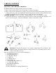
1. Install Left Tool Rest to the Left Wheel Guard. Use Knob, Screw, and
Nut to secure it in place as shown in Figure 1.
2. Install Right Tool Rest to the Right Wheel Guard using Knob, Screw,
and Nut.
3. Adjust the Tool Rests to within 1/16″ of the Grinding Wheel. To
adjust this distance, loosen Knobs and move Tool Rests.
4. Attach a Spark Arrestor to each Wheel Guard using a Screw as shown
in Figure 2. Adjust each Spark Arrestor to within 1/16” (0.0625″) of
the Grinding Wheel and tighten each Screw.
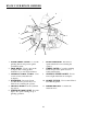
5. Attach Right Shield Arm to the Right Wheel Guard using Bolt and
Washers, see Figure 2.
6. Attach Left Shield Arm to the Left Wheel Guard using Bolt and
Washers.
7. Attach right Eye Shield to Right Shield Arm using Knob as shown in
Figure 3.
8. Attach left Eye Shield to Left Shield Arm using Knob.
WORK LIGHT
The Bench Grinder is provided with a Flexible Work Light to assist in
visibility of the workpiece.
The Bench Grinder is NOT provided with a light bulb for the Flexible Work Light.
To reduce the risk of fire, use a 120 volt, 40 Watt or less Track Light Bulb, Type R20, medium base
or equivalent (not included). DO NOT use a light bulb that extends past the end of the light housing.
CAUTION: The Flexible Work Light housing will remain hot for a few minutes after turning it “OFF”.
Avoid contact with housing until it is cool.
OPERATION
Figure 1
Tool Rest
Knob
Figure 2
Figure 3
Figure 3
Knob
Right
Shield
Arm
Eye
Shield
s