
Product Manual


6
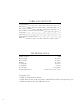
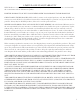
No. Part No. Description Qty
1 4288-001 Top Plate 1
2 4288-002 Hook 1
3 4288-003 Water Pot Assembly 1
4 4288-004 Column 1
5 4288-005 Base 1
6 4288-006 Set Screw M10x10 5
7 4288-007 M4x8 Phillips Pan Head Screw 1
8 4288-008 5 mm Inner Hex Wrench 1
9 4288-009 Hex Bolt M8x50 4
10 4288-010 Flat Washer D8 8
11 4288-011 Spring Washer D8 4
12 4288-012 Hex Nut M8 4
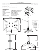
EXPLODED VIEW AND PARTS LIST
NOTE: The set screws (6) have been pre-installed on the pedestal. The extra hardware bag is provided for
mounting a bench grinder onto the pedestal stand.
1. Slide the column (4) into the base (5); secure by tightening the set screws (6) against the column, using the in-
cluded hex wrench.
2. Slide the water pot assembly (3) over the column (4). Tighten the set screw (6) to secure the water pot assembly.
3. Slide the top plate (1) over the column and secure with set screws (6). Set screws can be found pre-installed in
the base of the top plate.
4. Secure the base to the floor for maximum stability and safety. (Hardware not included)
5. Attach the hook (2) using the included phillips pan-head screw (7) and flat washer (10).
ASSEMBLY