
Product Manual

25
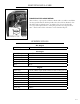
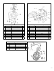
Fig. 11 - Panel Assembly
No. Part Number Description Qty
11-1 56125-1101 Status Display 1
11-2 56125-1102 LED Indicators 3
11-3 56125-1103 120V Socket Receptacles 1
11-4 56125-1104 Idle Switch 1
11-5 56125-1105 DC Socket Assembly 1
11-6 56125-1106 Parallel Socket 1
11-7 56125-1107 Parallel Socket 1
11-8 56125-1108 Grounding Terminal 1
11-10 56125-1110 Panel Screws 4
11-11 56125-1111 Control Panel Subassembly 1
11-12 56125-1112 Control Panel Wiring Harness 1
11-14 56125-1114 Front Panel Screws 4
11-15 56125-1115 Front Panel 1
11-16 56125-1116 Screw 4
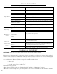
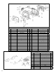
Fig. 13 - Rotor
No. Part Number Description Qty
13-1 56125-1301 Motor Shroud 1
13-2 56125-1302 Stator 1
13-3 56125-1303 Rotor 1
13-4 56125-1304 Impeller 1
13-5 56125-1305 Fan Cover 1
13-6 56125-1306 Fan Bolts 2
13-7 56125-1307 Stator Bolts 2
13-8 56125-1308 Shroud Bolt 4
13-9 56125-1309 Nut 1
13-10 56125-1310 Clamp 1
13-11 56125-1311 Screws 5
13-12 56125-1312 Rubber Cover 1
13-13 56125-1313 Screws 2
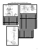
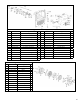
Fig. 11 - Panel Assembly
No. Part Number Description Qty
11-17 56125-1117 Choke Line 1
11-18 56125-1118 Screw 1
11-19 56125-1119 Choke Knob 1
11-20 56125-1120 Choke Control 1
11-21 56125-1121 Choke Lever 1
11-22 56125-1122 Choke Block 1
11-23 56125-1123 Steel Ball 1
11-24 56125-1124 Choke Spring 1
11-25 56125-1125 Fuel Cock Bracket 1
11-26 56125-1126 Screw 2
11-27 56125-1127 Fuel Valve 1
11-28 56125-1128 Bolt 1
11-29 56125-1129 Screw 1
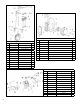
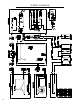
Fig. 11 - Panel Assembly