2000W INVERTER GENERATOR Getting Started Video Guide: bit.ly/56200i Model #56200i bit.ly/WENvideo IMPORTANT: Your new tool has been engineered and manufactured to WEN’s highest standards for dependability, ease of operation, and operator safety. When properly cared for, this product will supply you years of rugged, trouble-free performance. Pay close attention to the rules for safe operation, warnings, and cautions.
TABLE OF CONTENTS Generator Identification Service Record Introduction Safety Information Generator Components Generator Preparation Starting the Generator Stopping the Generator Subsequent Starting of the Generator Using the Generator Maintenance & Care Storage & Transport Specifications Troubleshooting Exploded View and Parts List Wiring Diagram Warranty Statement 2 3 3 4 4 7 8 10 12 12 13 15 19 19 20 21 27 28
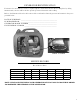
GENERATOR IDENTIFICATION If assistance for information or service is required, please contact the Customer Service Help Line by calling 800-232-1195; customer will be asked to provide generator information when calling. Refer to the illustration below for the location of the serial number. Record generator information in the spaces provided below.
INTRODUCTION Thank you for purchasing a WEN Generator. This manual provides information regarding the safe operation and maintenance of this product. Every effort has been made to ensure the accuracy of the information in this manual. WEN reserves the right to change this product, manual and specifications at any time without prior notice. Please keep this manual available to all users during the entire life of the generator.
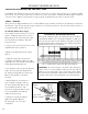
SAFETY INFORMATION For any questions regarding the hazard and safety notices listed in this manual or on the product, please call (800) 232-1195 M-F 8-5 CST before using the generator. DANGER: CARBON MONOXIDE Using a generator indoors CAN KILL YOU IN MINUTES. Generator exhaust contains carbon monoxide (CO). This is a poison gas you cannot see or smell. If you can smell the generator exhaust, you are breathing CO. But even if you cannot smell the exhaust, you could be breathing CO.
SAFETY INFORMATION GENERATOR SAFETY RULES (CONTINUED): 14) Do not touch hot surfaces. Pay attention to warning labels on the generator identifying hot parts of the machine. 20) Do not exceed the wattage capacity of the generator by plugging in more electrical devices than the unit can handle. 15) Allow generator to cool down after use before touching engine or areas of the generator that become hot during use. 21) Do not turn on electrical devices until after they are connected to the generator.
GENERATOR COMPONENTS Use the illustrations below to become familiar with the locations and functions of the various components and controls of this generator.
GENERATOR PREPARATION USING THE GENERATOR FOR THE FIRST TIME CAUTION: The following section describes the necessary steps to prepare the generator for use. If after reading this section, you are unsure about how to perform any of the steps please call (800) 232-1195 M-F 8-5 CST for customer service. Failure to perform these steps properly can damage the generator or shorten its life. STEP 1 - ADD OIL The generator is shipped without oil.
GENERATOR PREPARATION WARNING: This generator may emit highly flammable and explosive gasoline vapors, which can cause severe burns or even death if ignited. A nearby open flame can lead to explosion even if not directly in contact with gasoline. Step 2 - ADD GASOLINE Use fresh (within 30 days from purchase), lead-free gasoline with a minimum of 87 octane rating. Do not mix oil with gasoline. To add gasoline, follow these steps: 1. Make sure the generator is on a level surface. 2.
STARTING THE GENERATOR Before starting the generator, make sure you have read and performed the steps in the “Generator Preparation” section of this manual. If you are unsure about how to perform any of the steps in this manual please call (800) 232-1195 M-F 8-5 CST for customer service. DANGER: CARBON MONOXIDE - USING A GENERATOR INDOORS CAN KILL YOU IN MINUTES. Using a generator indoors CAN KILL YOU IN MINUTES. Generator exhaust contains carbon monoxide (CO). This is a poison gas you cannot see or smell.
STARTING THE GENERATOR STARTING THE ENGINE (FIG. 4) To start the generator, perform the following steps: 1. Unplug all electrical devices from the generator during starting. Otherwise it can be difficult to start the engine. 2. To maximize safety, make sure the generator is properly grounded (Refer to “Ground the Generator”). Fig. 4A 3. Check the oil and fuel levels. 4. Turn the ECO-MODE switch to “OFF.” 5. Open vacuum relief valve on top of fuel cap (Figure 4A). Rotate clockwise to the “ON” position. 6.
STOPPING THE GENERATOR TO STOP THE GENERATOR 1. Turn off all electrical devices prior to unplugging them from the generator. Unplugging running devices can cause damage to the generator. 2. Turn the 3-in-1 knob to the “OFF” position (Fig. 4E). 3. Close the vacuum relief valve on top of fuel cap (Fig. 4A). Rotate counterclockwise to the “OFF” position. WARNING: Allow the generator to cool for several minutes before touching areas that become hot during use.
SUBSEQUENT STARTING OF THE GENERATOR Step 3 - GROUND THE GENERATOR WARNING: Failure to properly ground the generator increases the chances of electric shock. Ground the generator by tightening the grounding nut on the front control panel against a grounding wire (Fig. 3). A generally acceptable grounding wire is a No. 12 AWG (American Wire Gauge) stranded copper wire. This grounding wire should be connected at the other end to a copper, brass, or steel-grounding rod that is driven into the earth.
USING THE GENERATOR If the electrical specifications are not available for your electronic devices, estimate the watts requirement of the device by using the chart in Figure 6. When the rated wattage requirement of each electrical device has been determined, add these numbers to find the total rated wattage needed. If this number exceeds the rated wattage of the generator, DO NOT connect all these devices.
USING THE GENERATOR CAUTION: Do not connect 50Hz loads to the generator. SOME NOTES ABOUT POWER CORDS Long or thin cords can drain the power provided to an electrical device by the generator. When using such cords, allow for a slightly higher rated wattage requirement by the electrical device. See Figure 7 for recommended cords based on the power requirement of the electrical device. Device Requirements Amps Watts (120V) 2.5 300 5 600 7.5 900 10 1200 15 1800 *NR = Not Recommended Max.
MAINTENANCE HIGH ALTITUDE OPERATION ABOVE 3000 FEET The fuel system on this generator may be affected by operation at high altitudes. Proper operation can be ensured by installing an altitude kit at altitudes higher than 3000 feet above sea level. At elevations above 8000 feet, the engine may experience a decrease in performance, even with the proper altitude kit. Operating this generator without said kit may increase the engine’s emissions and decrease both fuel economy and performance.
MAINTENANCE & CARE CHANGING/ADDING OIL Change the oil according to the Recommended Maintenance Schedule in Figure 9 using the maintenance hatch door found on the side panel of the generator.. Change the oil when the engine is warm. This will allow for complete drainage. Change oil more often if operating under heavy load or high ambient temperatures. It is also necessary to drain the oil from the crankcase if it has become contaminated with water or dirt. The oil capacity of the generator engine is 0.
MAINTENANCE & CARE SPARK PLUG MAINTENANCE (Fig. 11) The spark plug is important for proper engine operation. A good spark plug should be intact, free of deposits, and properly gapped. Refer to Recommended Maintenance Schedule in Figure 8. To inspect the spark plug: 1. Remove side panel. 2. Remove spark plug boot. Be careful not to tear insulation or wire. 3. Unscrew the spark plug from the engine using the spark plug wrench provided. There is limited space for the wrench to turn.
STORAGE & TRANSPORT PROCEDURES CAUTION: Never place any type of storage cover on the generator while it is still hot. If the generator is being stored for short periods of time (30 to 60 days), add stabilized fuel to the fuel tank until full. NOTE: Filling the tank reduces the amount of air in the tank and helps fight deterioration of fuel. Run the engine for 2 – 3 minutes allowing stabilized fuel mixture to circulate through the carburetor.
TROUBLESHOOTING IMPORTANT: If trouble persists, please call our customer help line at (800) 232-1195 M-F 8-5 Central Time. Problem Cause Solution Engine will not start Engine switch in “OFF” position Set engine switch to “CHOKE” position. Engine is filled with contaminated or old fuel Change the fuel in the tank. Not enough oil in crankcase Add or replace oil. Air cleaner is dirty. Clean or replace air cleaner. Spark plug is dirty. Spark plug is broken. Clean spark plug. Replace spark plug.
EXPLODED VIEW AND PARTS LIST No. 1-1 1-2 1-3 1-5 1-6 Fig. 1 - Engine Part Number Description 56200-0101 Engine 56200-0102 Screw 56200-0103 Cap 56200-0105 Fuel Tube 56200-0106 Bolt Qty. 1 5 1 1 1 Fig. 2 - Fuel Tank No.
No. 4-1 4-2 4-3 4-4 4-6 4-7 4-8 4-9 4-10 4-11 4-12 4-13 4-14 4-16 4-17 4-20 4-21 4-22 4-23 4-24 4-25 4-26 4-27 22 Fig.
No. 5-1 5-2 5-3 5-4 5-5 5-6 5-7 5-8 5-9 5-10 5-11 5-12 5-15 5-16 5-17 5-18 Fig. 5 - Inverter Assembly Part Number Description Qty.
No. 7-1 7-2 7-3 7-4 7-5 7-6 7-7 7-8 7-9 Fig. 7 - Rotor/Stator Part Number Description 56200-0701 Bolt 56200-0702 Motor Shroud 56200-0703B Stator Comp 56200-0704 Rotor Comp 56200-0705 Impeller 56200-0706 Bolt 56200-0707 Pin 56200-0708 Bolt 56200-0709 Nut Qty. 5 1 1 1 1 2 2 2 1 No. 8-1 8-2 8-3 8-4 8-5 8-6 8-7 8-8 8-9 8-10 8-11 8-12 8-13 8-14 No. 9-1 9-2 9-3 9-4 9-5 9-6 9-7 9-8 24 Fig.
No. 10-1 10-3 10-4 10-5 10-6 10-7 No. 12-1 12-2 12-3 12-4 12-6 12-8 12-9 12-10 Fig. 10 - Piston Ring Set & Crankshaft Part Number Description 56200-1001 Crankshaft 56200-1002 Connecting Rod 56200-1003 Piston 56200-1004 Piston Pin Clip 56200-1005 Piston Pin Clip 56200-1007 Piston Ring Assembly Qty. 1 1 1 2 1 1 Fig. 12 - Recoil Starter Part Number Description Qty.
Fig. 14 - Air Cleaner No. Part Number Description Qty. 14-1 56200-1401 Air Cleaner 1 14-2 56200-1402 Air Cleaner Gasket 1 14-3 56200-1403 Air Cleaner Intake Duct 1 14-4 56200-1404 Nut 2 14-5 56200-1405 Stud 1 14-6 56200-1406 Stud 1 14-7 56200-1407B Air Cleaner Element 1 14-8 56200-1408B Seal Ring 1 No. 16-1 16-2 16-3 16-4 16-5 16-6 16-7 16-8 16-9 16-10 26 No. 15-1 15-2 15-3 15-4 15-5 15-6 15-13 15-15 Fig.
Gr G L Br G/Y R/W R B W O Y Gray Green Blue Brown Green/Yellow Red/White Red Black White Orange Yellow WIRING DIAGRAM 27
WARRANTY STATEMENT Remember to save the receipt and to accurately fill out and mail the product registration card. Proof of purchase is required for all warranty work. WEN® generators are under warranty to be free from defects in materials and workmanship for a period of two (2) years from date of original purchase. Generators used for Commercial or Rental use have a warranty period of 90 days from date of original purchase.