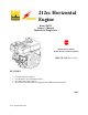
212cc Horizontal Engine Item # 56212 Owner’s Manual Manual del Propietario Questions? Problems? Please call our customer help line: (800) 232-1195 M-F 8-5 CST FEATURES • • • • Low Oil Automatic Shutoff Circuit Breaker for Overload Protection 0.9 Gallon Fuel Tank Capacity Meets EPA Phase III Emission Standards and CARB Emission Standards 2015 www.wenproducts.
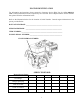
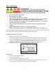
ENGINE IDENTIFICATION For information and questions, please contact the Customer Service Help Line by calling 800-2321195. Certain information will be requested by the Customer Service Representative and to facilitate that, please fill in the information below. Refer to the illustration below for the location of Serial Number. Record engine information in the spaces provided below.
TABLE OF CONTENTS ENGINE IDENTIFICATION ..........................................................................................................i SERVICE RECORD .........................................................................................................................i INTRODUCTION ............................................................................................................................ 1 SAFETY INFORMATION....................................................................
INTRODUCTION Thank You for Purchasing a WEN Power TM Product. . This manual provides information regarding the safe operation and maintenance of this product. Every effort has been made to ensure the accuracy of the information in this manual. WEN Power TM reserves the right to change this product and specifications at any time without prior notice. Please keep this manual available to all users during the entire life of the product.
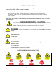
SAFETY INFORMATION Before operating this engine read and observe all warnings, cautions, and instructions on this sheet, on the engine, and in the Owner’s Manual. NOTE: The following safety information is not meant to cover all possible conditions and situations that may occur. Read the entire Owner’s Manual for safety and operating instructions. Failure to follow instructions and safety information could result in serious injury or death.
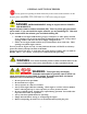
GENERAL SAFETY PROCEDURES For any questions regarding the hazard and safety notices listed in this manual or on the product, please call (800) 232-1195 M-F 8-5 CST before using the engine. DANGER: CARBON MONOXIDE. Using an engine indoors CAN KILL YOU IN MINUTES. Engine exhaust contains carbon monoxide (CO). This is a poison gas you cannot see or smell. If you can smell the engine exhaust, you are breathing CO. But even if you cannot smell the exhaust, you could be breathing CO.
WARNING: This engine produces heat when running. Temperatures near exhaust can exceed 150º F (65º C). • • Do not touch hot surfaces. Pay attention to warning labels on the engine identifying hot parts of the machine. Allow engine to cool down after use before touching engine or areas of the engine that become hot during use. CAUTION: Misuse of this engine can damage it or shorten its life. • • • Use engine only for its intended purposes. Operate only on dry, level surfaces.
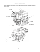
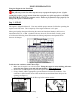
ENGINE COMPONENTS Please familiarize yourself with the locations and functions of the various components and controls of your engine.
ENGINE PREPARATION Using the Engine for the First Time The following section describes steps necessary to prepare the engine for use. If after reading this section, you are unsure about how to perform any of the steps please call (800) 232-1195 M-F 8-5 CST for customer service. Failure to perform these steps properly can damage the engine or shorten its life. Step 1 - Fill Oil The engine is shipped without oil. User must add the proper amount of oil before operating the engine for the first time.
Step 2- Add Gasoline WARNING: This engine may emit highly flammable and explosive gasoline vapors, which can cause severe burns or even death if ignited. A nearby open flame can lead to explosion even if not directly in contact with gasoline. • • • • • • • • Do not operate near open flame. Do not smoke near engine. Always operate on a firm, level surface. Always turn engine off before refueling. Allow engine to cool for at least 2 minutes before removing fuel cap.
STARTING THE ENGINE Before starting the engine, make sure you have read and performed the steps in the “Engine Preparation” section of this manual. If you are unsure about how to perform any of the steps in this manual please call (800) 232-1195 M-F 8-5 CST for customer service. DANGER: CARBON MONOXIDE. Using an engine indoors CAN KILL YOU IN MINUTES. Engine exhaust contains carbon monoxide (CO). This is a poison gas you cannot see or smell. If you can smell the engine exhaust, you are breathing CO.
SUBSEQUENT STARTING OF THE ENGINE If this is not the first time using the engine, user should take the following steps to prepare it for operation. IMPORTANT: At this point the user should be familiar with the procedures described in the section titled “Using the Engine for the First Time.” If the user has not yet read this section, go back and read it now. Step 1- Check the Oil Oil consumption is normal during engine usage. The engine is equipped with a low-oil shutoff to protect it from damage.
HIGH ALTITUDE OPERATION ABOVE 3000 FEET The fuel system on this engine may be influenced by operation at higher altitudes. Proper operation can be ensured by installing an altitude kit at altitudes higher than 3000 feet above sea level. At elevations above 8000 feet, the engine may experience decrease performance, even with the proper main jet. Operating this engine without the proper altitude kit installed may increase the engine’s emissions and decrease fuel economy and performance.
STOPPING THE ENGINE To stop the engine: 1. Turn the engine switch to the “OFF” position. 2. Turn the fuel valve to the “OFF” position. WARNING: Allow the engine to cool for several minutes before touching areas that become hot during use. CAUTION: Allowing gasoline to sit in the engine tank for long periods of time without use can make it difficult to start the engine in the future. Never store engine for extended periods of time with fuel in the tank.
Cleaning the Engine Never clean the engine when it is running! Never clean with a bucket of water or a hose. Water can get inside the working parts of the engine and cause a short circuit or corrosion. Always try to use the engine in a cool, dry place. If the engine becomes dirty, clean the exterior with a damp cloth, a soft brush, vacuum or pressurized air. Checking the Oil Check the oil level of the engine according to the Recommended Maintenance Schedule in Figure 7.
1. Make sure the engine is on a level surface. Tilting the engine to assist in filling will cause oil to flow into engine areas and will cause damage. Keep engine level! 2. Remove the oil filler/dipstick cap from the engine as shown in figure 8 above. 3. Using a funnel, add the appropriate type and amount of oil into the crankcase. The crankcase is full when the oil level has reached the second thread from the lip of the opening (see figure 10). 4. Check for oil leaks.
0.7-0.8 mm (0.028-0.031 in) Figure 11- Measuring the spark plug gap Recommended Spark Plug: NGK- BP7ES, Torch- F6TC Draining the Fuel Tank Clean fuel tank each year or before storing the engine for extended periods of time. To drain the fuel tank and carburetor: 1. Turn the fuel valve to the “OFF” position. Move the engine in a well-ventilated area away from ignition sources. 2. Place a funnel leading to a proper gasoline container below the carburetor. 3.
STORAGE / TRANSPORT PROCEDURES CAUTION: Never place any type of storage cover on the engine while it is still hot. If the engine is being stored for short periods of time (30 – 60 days), add stabilized fuel to the fuel tank until full. NOTE: Filling the tank reduces the amount of air in the tank and helps reduce deterioration of fuel. Run the engine for 2 – 3 minutes allowing stabilized fuel mixture to circulate through the carburetor.
SPECIFICATIONS Displacement Max. Output Max. Torque Engine Type Cooling System Fuel Type Capacity Type SAE Engine Oil Capacity Lubrication System Run Time @ 50% Load with full tank Sound Level at 22 feet Bore x Stroke Compression Ratio Rotation viewed from PTO (power takeoff - the output shaft) Shaft Keyway Shaft End Tapped Type Spark Plug Gap Intake Valve Clearance Exhaust Idle Speed Dimensions Weight 212cc 4.
MOUNTING HOLE DIAGRAM POWER TAKE-OFF DIAGRAM 17
TROUBLESHOOTING IMPORTANT: If trouble persists please call our customer help line at (800) 232-1195 M-F 8-5 Central Time. Problem Engine will not start Cause Fuel Related: No fuel in tank or fuel valve closed. Choke not in CHOKE position, cold engine. Solution Fuel Related: Fill fuel tank and open fuel valve. Move Choke to CHOKE position. Gasoline with more than 10% ethanol used. (E15, E20, E85, etc.) Clean out ethanol rich gasoline from fuel system. Replace components damaged by ethanol.
Problem Engine will not start Cause COMPRESSION RELATED: Cylinder not lubricated. Problem after long storage periods. Solution COMPRESSION RELATED: Pour tablespoon of oil into spark plug hole. Crank engine a few times and try to start again. Loose or broken spark plug. (Hissing noise will occur when trying to start.) Tighten spark plug. If that does not work, replace spark plug. If problem persists, may have head gasket problem. Loose cylinder head or damaged head gasket.
Problem Engine stops when under heavy load Cause Dirty air filter Engine running cold. Solution Clean or replace element. Allow engine to warm up prior to operating equipment. Engine knocks Old or low quality gasoline. Fill fuel tank with fresh 87+ octane unleaded gasoline. Engine overloaded. Do not exceed equipment’s load rating. Incorrect spark timing, deposit buildup, worn engine, or other mechanical problems. Have qualified technician diagnose and service engine.
EXPLODED VIEW AND PARTS LIST FIG.
FIG.
FIG.3 CRANKCASE COVER ITEM Fig03-1 Fig03-2 Fig03-3 Fig03-4 Fig03-5 Fig03-6 Fig03-8 Fig03-9 STOCK # 56212-0301 56212-0302 56212-0303 56212-0304 56212-0305 56212-0306 56212-0308 56212-0309 DESCRIPTION COVER, CRANKCASE BEARING SEAL, OIL GASKET, CRANKCASE PIN DIPSTICK ASSEMBLY, OIL PLUG ASSEMBLY, ENGINE OIL BOLT QTY 1 1 1 1 2 1 1 6 FIG.
FIG.
FIG.
FIG.7 RECOIL STARTER ITEM Fig07-1 Fig07-2 STOCK # 56212-0701 56212-0702 DESCRIPTION BOLT STARTER ASSEMBLY, RECOIL QTY 3 1 DESCRIPTION SHROUD SHROUD, CYLINDER BODY SHIELD,LOWER PROTECTOR, OIL ENGINE SWITCH BOLT BOLT COLLAR BOLT BOLT QTY 1 1 1 1 1 2 1 1 1 4 FIG.
FIG.9 CARBURETOR ITEM Fig09-1 Fig09-2 Fig09-3 Fig09-33 Fig09-34 STOCK # 56212-0901 56212-0902 56212-0903 56212-0933 56212-0934 DESCRIPTION CARBURETOR ASSEMBLY GASKET, AIR CLEANER GASKET, CARBURETOR PLATE, CARBURETOR INSULATOR GASKET, CARBURETOR INSULATOR QTY 1 1 1 1 1 FIG.
FIG.11 MUFFLER ASSY ITEM Fig11-1 Fig11-2 Fig11-3 STOCK # 56212-1101 56212-1102 56212-1103 DESCRIPTION GASKET, EXHAUST OUTLET NUT MUFFLER ASSEMBLY QTY 1 2 1 DESCRIPTION TANK, FUEL STRAINER,FUEL COVER, FUEL TANK OUTLET ASSEMBLY, FUEL TANK OIL COLLAR TUBE, FUEL BOLT NUT JACKET, RUBBER QTY 1 1 1 1 2 1 1 2 1 FIG.
FIG.13 FLYWHEEL & IGNITION COIL ITEM Fig13-1 Fig13-2 Fig13-3 Fig13-4 Fig13-7 Fig13-9 STOCK # 56212-1301 56212-1302 56212-1303 56212-1304 56212-1307 56212-1309 DESCRIPTION NUT, FLYWHEEL PULLEY,STARTER IMPELLER FLYWHEEL ASSEMBLY BOLT COIL, IGNITION QTY 1 1 1 1 2 1 FIG.
NOTES: 30
WARRANTY STATEMENT FOR WEN®ENGINES WEN Power™ engines are warranted (to the original purchaser) to be free from defects in materials and workmanship for a period of two (2) years from the date of original purchase. Engines used for commercial or for rental have a warranty period of 90 days from date of original purchase. Please fill out and mail the enclosed warranty card and mail it to Power Pro Technology along with a copy of the receipt. The information is required to process warranty claims.