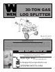
30-TON GAS LOG SPLITTER Model # 56230 bit.ly/WENvideo IMPORTANT: Your new tool has been engineered and manufactured to WEN’s highest standards for dependability, ease of operation, and operator safety. When properly cared for, this product will supply you years of rugged, trouble-free performance. Pay close attention to the rules for safe operation, warnings, and cautions. If you use your tool properly and for intended purpose, you will enjoy years of safe, reliable service.
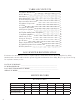
TABLE OF CONTENTS Log Splitter Identification Service Record Introduction Safety Information General Safety Procedures Important Safety Instructions Log Splitter Components Assembly Log Splitter Preparation Starting the Log Splitter Stopping the Log Splitter Subsequent Starting of the Log Splitter Using the Log Splitter Maintenance & Care Storage & Transport Specifications Engine Exploded View and Parts List Log Splitter Exploded View and Parts List Warranty Statement 2 2 3 3 4 5 7 8 13 15 17 17 19 22 26 2
INTRODUCTION Thank You for Purchasing a WEN® Product. This manual provides information regarding the safe operation and maintenance of this product. Every effort has been made to ensure the accuracy of the information in this manual. WEN® reserves the right to change this product and specifications at any time without prior notice. Please keep this manual available to all users during the entire life of the log splitter.
GENERAL SAFETY PROCEDURES For any questions regarding the hazard and safety notices listed in this manual or on the product, please call (800) 232-1195 M-F 8-5 CST before using the log splitter. DANGER: CARBON MONOXIDE Using a engine indoors CAN KILL YOU IN MINUTES. Engine exhaust contains carbon monoxide (CO). This is a poison gas you cannot see or smell. If you can smell the engine exhaust, you are breathing CO. But even if you cannot smell the exhaust, you could be breathing CO.
GENERAL SAFETY PROCEDURES WARNING: The engine produces heat when running. Temperatures near exhaust can exceed 1500 F (650 C). Do not touch hot surfaces. Allow engine to cool down after use before touching any areas of the log splitter that become hot during use (such as the engine). CAUTION: Misuse of this log splitter can damage it or shorten its life. Only use log splitter for its intended purposes. Operate only on level surfaces. Allow engine to run for several minutes before using the log splitter.
IMPORTANT SAFETY INSTRUCTIONS 10. Only uses square log ends: logs that are not cut square can slide out while splitting and become a safety hazard or cause excessive force to log splitter components. Use a chain saw to cut logs square on each end before attempting to split them. 11. Single log: never attempt to split more than one log at a time. Pieces of log can unexpectedly be thrown from the machine causing serious injury. 12. Split along grain: do not use the log splitter to split logs across the grain.
LOG SPLITTER COMPONENTS Use the illustrations below to become familiar with the locations and functions of the various components and controls of this log splitter.
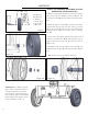
ASSEMBLY 1A 1B 2 3 4 5 1A - Bearing 1B - Bearing 2 - Washer 3 - Castle Nut 4 - Cotter Pin 5 - Hub Cap Figure 1 STEP 1 - ATTACHING THE TIRES TO THE HYDRAULIC TANK (FIGURE 1) 1. Slide a bearing (1A) and the tire onto axle with the valve stem (valve for inflation) facing out (Figure 1A) (bearings 1A and 1B may already be mounted on the tire). 2. Slide the other bearing (1B), a washer (2) and the slotted castle nut (3) onto the axle. Using a wrench, tighten the nut.
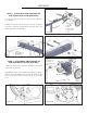
ASSEMBLY 3 STEP 2 - ATTACHING THE TOW BAR TO THE HYDRAULIC TANK (FIGURE 2) 1. Lock the support leg (4) in its downward position before starting. 2 1 5 2. Slide the tow bar (1) into the pivot mount (3). Fasten it in place using the included bolts (2) and nuts (5) as shown in Figures 2A and 2B. 4 Figure 2 Figure 2A STEP 3 - ATTACHING THE ENGINE TO THE HYDRAULIC TANK (FIGURE 3) 1. Place the engine (1) as shown in position on top of the engine mount plate (5). Figure 2B 1. Engine 2. Nuts (4) 3.
ASSEMBLY Figure 4 1 STEP 4 - ASSEMBLING THE LOG CRADLES (FIGURE 4) Attach the two log cradles (2) to beam using four bolts (3) and four locknuts (1). 2 Figure 4A 1. Nuts (4) 2. Log Cradles (2) 3. Bolts (4) 3 Figure 4B STEP 5 - ASSEMBLE THE BEAM LOCK BRACKET (FIGURE 5) 1. Run the two hoses emerging from either side of the control valve to the underside of the log splitter as shown in Figure 5A (next page). 2. Fasten the beam lock bracket using the included bolts and nuts.
ASSEMBLY Figure 5B 1. Pivot Mount 2. Beam Pivot Pin 3. Cotter Pin 4. Beam Assembly 5.
ASSEMBLY STEP 7 - CONNECTING THE HOSES WARNING: Be extremely careful when connecting the hoses. Connecting the hose to the wrong port could quickly ruin your log splitter and also runs the risk of inflicting an unwanted injury. Double check that the hoses are running to the correct inlets and outlets before starting the log splitter. 1. Connect one end of the suction hose (2) to the tank suction port (1) and the other end to the pump inlet (3) as shown in Figure 7A.
LOG SPLITTER PREPARATION USING THE LOG SPLITTER FOR THE FIRST TIME The following section describes steps necessary to prepare the log splitter for use. If after reading this section, you are unsure about how to perform any of the steps please call (800) 232-1195 M-F 8-5 CST for customer service. Failure to perform these steps properly can damage the log splitter or shorten its life. Step 1 - ADD OIL The log splitter is shipped without oil.
LOG SPLITTER PREPARATION Step 2 - ADD GASOLINE WARNING: The engine may emit highly flammable and explosive gasoline vapors, which can cause severe burns or even death if ignited. A nearby open flame can lead to explosion even if not directly in contact with gasoline. Use fresh (within 30 days from purchase) lead-free gasoline with a minimum of 87 octane rating. Do not mix oil with gasoline. To add gasoline, follow these steps: 1. Make sure the log splitter is on a level surface. 2.
LOG SPLITTER PREPARATION HOW TO ADD HYDRAULIC FLUID 1. Remove hydraulic dipstick. 2. Fill hydraulic tank with 10 wt AW32, ASLE H-150, or ISO 32 oil. Use a funnel if need. 3. Remove hydraulic dipstick and check the level. Note: Do not screw in dipstick when checking levels. 3. Start engine and use split control lever to extend and retract wedge five times to remove air from the hydraulic system. 4. With wedge retracted, check oil level again.
STARTING THE LOG SPLITTER STARTING THE ENGINE To start the engine, perform the following steps: 1. Check the oil, fuel and hydraulic fluid levels. 2. Push the Fuel Valve to “ON” position, moving the fuel valve over to the right as shown. 3. Move the Choke Lever to “START” position by sliding it over to the left. 4. Set the engine switch to the “ON” position. 5. Slide the Throttle Lever 1/3 away from the SLOW position (the turtle). 6.
STOPPING THE LOG SPLITTER TO TURN OFF THE LOG SPLITTER WARNING: Allow the engine to cool for several minutes before touching areas that become hot during use. CAUTION: Allowing gasoline to sit in the fuel tank for long periods of time can make it difficult to start the engine in the future. Never store the log splitter for extended periods of time with fuel in the fuel tank. 1. Retract the wedge completely to keep the rod protected from corrosion. 2.
SUBSEQUENT STARTING OF THE LOG SPLITTER WARNING: This engine may emit highly flammable and explosive gasoline vapors, which can cause severe burns or even death if ignited. A nearby open flame can lead to explosion even if not directly in contact with fuel. • Do not operate near open flame. • Do not smoke near log splitter. • Always operate on a firm, level surface. • Always turn log splitter off before refueling. Allow engine to cool for at least 2 minutes before removing fuel cap.
USING THE LOG SPLITTER WARNING: It is important to select an appropriate work site and properly set up the log splitter in order to minimize the risk of slips and falls, equipment rolling or tipping over, carbon monoxide poisoning, and accidental fires. SELECT LOCATION Make sure to find a dry level surface with good footing for operation. Stay clear of areas with mud, ice, tall grass, weeds, brush, or snow. Always use the log splitter outdoors, away from air intakes.
USING THE LOG SPLITTER SET TO VERTICAL LOCK Pull out horizontal lock latch rod, grasp and lift beam until it rotates into vertical position. WARNING: Crush hazard. The beam is heavy – do not let it just drop. It could crush fingers or cause damage to the splitter. Vertical Lock Lock in vertical position using latch rod through the vertical lock.
USING THE LOG SPLITTER EXTENDING AND RETURNING THE WEDGE CAUTION: Remove both hands from log before activating Split Control Lever. Use only your hand to operate the Split Control Lever. Never use any other body part, or a rope, cable, or other remote device to actuate the control. Many accidents occur when there is more than one person involved in loading and operating the log splitter. Only one person should operate the controls.
MAINTENANCE & CARE Proper routine maintenance of the log splitter will help prolong the life of the machine. Please perform maintenance checks and operations according to the schedule outlined in the chart below. If there are any questions about the maintenance procedures listed in this manual, please call (800) 232-1195 M-F 8-5CT. CAUTION: Never perform maintenance operations while the engine is running.
MAINTENANCE & CARE CLEANING THE LOG SPLITTER Never clean the log splitter when it is running! Never clean with a bucket of water or a hose. If the log splitter becomes dirty, clean the exterior with a damp cloth, a soft brush, a vacuum or pressurized air. CHECKING THE OIL Check the oil level of the engine according to the Recommended Maintenance Schedule (page 22). The engine is equipped with an automatic shutoff to protect it from running on low oil.
MAINTENANCE & CARE To refill the crankcase with oil, follow these steps: 1. Make sure the log splitter is on a level surface. 2. Remove the dipstick from the engine. 3. Using a funnel or appropriate dispenser, add the correct amount of oil into the crankcase. The engine is equipped with a low-oil pressure sensor and will not start if the amount of oil is insufficient. 4. Reinstall dipstick. NOTE: Never dispose of used motor oil in the trash or down a drain.
MAINTENANCE & CARE SPARK PLUG MAINTENANCE The spark plug is important for proper engine operation. A good spark plug should be intact, free of deposits, and properly gapped. Refer to Recommended Maintenance Schedule. To inspect the spark plug: 1. Remove spark plug boot. Be careful not to tear insulation or wire. 2. Unscrew the spark plug from the engine using the spark plug wrench provided. There is limited space for the wrench to turn.
STORAGE & TRANSPORT Return to horizontal. If in the vertical position, turn off engine and return log splitter to the horizontal position for greater stability during transportation. Avoid contact with the muffler and the surrounding area, as these parts may be hot. Remove engine debris. Debris on a hot engine can be a fire hazard. With the engine off, clear debris and chaff from engine cylinder head, cylinder head fins, blower housing rotating screen, and muffler areas. Avoid contact with hot muffler.
SPECIFICATIONS Engine Engine type Spark plug gap Spark plug torque Displacement Fuel tank capacity Oil capacity Lubrication system Run time on 50% load Noise rating Spark plug 4 stroke, OHV, single cylinder with forced air cooling system 0.6 - 0.7 mm (0.024 - 0.028 in) 1/2 - 3/4 turn after gasket contacts base or 15 ft.lb 212 cc 1 gallon 87 octane minimum 0.37 quarts (0.35 liters) Splash lubrication 4 hours 63 dB at 22 feet A5RTC Log Splitter Model Ram Force Continuous Force Max. Log Length Max.
ENGINE EXPLODED VIEW AND PARTS LIST FIG.1 CYLINDER HEAD ASSEMBLY ITEM Fig01-1 Fig01-2 Fig01-3 Fig01-4 Fig01-5 Fig01-6 Fig01-7 Fig01-8 Fig01-9 Fig01-10 Fig01-11 STOCK # 56212-0101 56212-0102 56212-0103 56212-0104 56212-0105 56212-0106 56212-0107 56212-0108 56212-0109 56212-0110 56212-0111 DESCRIPTION GASKET, CYLINDER HEAD COVER, CYLINDER HEAD GASKET, CYLINDER HEAD COVER TUBE, BREATHER BOLT STUD STUD PIN BOLT, CYLINDER HEAD PLUG, SPARK HEAD ASSEMBLY, CYLINDER QTY 1 1 1 1 4 2 2 2 4 1 1 FIG.
ENGINE EXPLODED VIEW AND PARTS LIST FIG.3 CRANKCASE COVER ITEM Fig03-1 Fig03-2 Fig03-3 Fig03-4 Fig03-5 Fig03-6 Fig03-8 Fig03-9 STOCK # 56212-0301 56212-0302 56212-0303 56212-0304 56212-0305 56212-0306 56212-0308 56212-0309 DESCRIPTION COVER, CRANKCASE BEARING SEAL, OIL GASKET, CRANKCASE PIN DIPSTICK ASSEMBLY, OIL PLUG ASSEMBLY, ENGINE OIL BOLT QTY 1 1 1 1 2 1 1 6 DESCRIPTION CRANKSHAFT ASSEMBLY QTY 1 FIG.
ENGINE EXPLODED VIEW AND PARTS LIST FIG.5 PISTON & CONNECTING ROD ITEM Fig05-1 Fig05-2 Fig05-3 Fig05-4 Fig05-6 Fig05-7 Fig05-8 STOCK # 56212-0501 56212-0502 56212-0503 56212-0504 56212-0506 56212-0507 56212-0508 DESCRIPTION CLIP, PISTON PIN PISTON PIN, PISTON ROD, CONNECTING RING, THE FIRST RING, THE SECON RING SET, OIL QTY 2 1 1 1 1 1 1 FIG.
ENGINE EXPLODED VIEW AND PARTS LIST FIG.7 RECOIL STARTER ITEM Fig07-1 Fig07-2 STOCK # 56212-0701 56212-0702 DESCRIPTION BOLT STARTER ASSEMBLY, RECOIL QTY 3 1 DESCRIPTION SHROUD SHROUD, CYLINDER BODY SHIELD,LOWER PROTECTOR, OIL ENGINE SWITCH BOLT BOLT COLLAR BOLT BOLT QTY 1 1 1 1 1 2 1 1 1 4 FIG.
ENGINE EXPLODED VIEW AND PARTS LIST FIG.9 CARBURETOR ITEM Fig09-1 Fig09-2 Fig09-3 Fig09-33 Fig09-34 STOCK # 56212-0901 56212-0902 56212-0903 56212-0933 56212-0934 DESCRIPTION CARBURETOR ASSEMBLY GASKET, AIR CLEANER GASKET, CARBURETOR PLATE, CARBURETOR INSULATOR GASKET, CARBURETOR INSULATOR QTY 1 1 1 1 1 FIG.
ENGINE EXPLODED VIEW AND PARTS LIST FIG.11 MUFFLER ASSY ITEM Fig11-1 Fig11-2 Fig11-3 STOCK # 56212-1101 56212-1102 56212-1103 DESCRIPTION GASKET, EXHAUST OUTLET NUT MUFFLER ASSEMBLY QTY 1 2 1 DESCRIPTION TANK, FUEL STRAINER,FUEL COVER, FUEL TANK OUTLET ASSEMBLY, FUEL TANK OIL COLLAR TUBE, FUEL BOLT NUT JACKET, RUBBER QTY 1 1 1 1 2 1 1 2 1 FIG.
ENGINE EXPLODED VIEW AND PARTS LIST FIG.13 FLYWHEEL & IGNITION COIL ITEM Fig13-1 Fig13-2 Fig13-3 Fig13-4 Fig13-7 Fig13-9 STOCK # 56212-1301 56212-1302 56212-1303 56212-1304 56212-1307 56212-1309 DESCRIPTION NUT, FLYWHEEL PULLEY,STARTER IMPELLER FLYWHEEL ASSEMBLY BOLT COIL, IGNITION QTY 1 1 1 1 2 1 FIG.
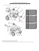
LOG SPLITTER EXPLODED VIEW AND PARTS LIST BEAM ASSEMBLY ITEM 1 2 3 4 5 6 7 8 9 10 11 12 13 14 15 16 17 18 19 20 21 22 STOCK# 56227-0101 56222-0102 56222-0103 56222-0104 56222-0105 56222-0106 56222-0107 56222-0108 56222-0109 56222-0110 56222-0111 56222-0112 56222-0113 56222-0114 56222-0115 56222-0116 56222-0117 56222-0118 56222-0119 56222-0120 56222-0121 56222-0122 DESCRIPTION CYLINDER ASSEMBLY HIGH PRESSURE FITTING FOR CYLINDER HIGH PRESSURE HOSE FOR CYLINDER VALVE MOUNT FITTING HIGH PRESSURE FITTING FO
LOG SPLITTER EXPLODED VIEW AND PARTS LIST TOW BAR ASSEMBLY ITEM 1 2 3 4 5 6 7 8 9 10 11 12 13 14 36 STOCK # 56222-0201 56222-0202 56222-0203 56222-0204 56222-0205 56222-0206 56222-0207 56222-0208 56222-0209 56222-0210 56222-0211 56222-0212 56222-0213 56222-0214 DESCRIPTION QTY TONGUE 1 BOLT M6X15 2 MANUAL TUBE 1 PIN CATCH 1 NUT M12 2 BOLT M12X80 2 BALL COUPLER ASSEMBLY 1 BOLT M10X90 1 WASHER M10 2 NUT NYLOCK M10 1 SAFETY CHAIN 2 SUPPORT LEG 1 NUT NYLOCK M8 1 BOLT M8X75 1
LOG SPLITTER EXPLODED VIEW AND PARTS LIST HYDRAULIC TANK & TIRE ASSEMBLY ITEM 1 2 3 4 5 6 7 8 9 10 11 STOCK # 56222-0301 56222-0302 56222-0303 56222-0304 56222-0305 56222-0306 56222-0307 56222-0308 56222-0309 56222-0310 56222-0311 DESCRIPTION TANK VENT CAP ASSEMBLY FLAT WASHER TIRE ASSEMBLY 4.
LOG SPLITTER EXPLODED VIEW AND PARTS LIST ENGINE & PUMP ASSEMBLY ITEM 1 2 3 4 5 6 7 8 9 10 11 12 13 14 38 STOCK# 56222-0401 56222-0402 56222-0403 56222-0404 56222-0405 56222-0406 56222-0407 56222-0408 56227-0409 56222-0410 56222-0411 56222-0412 56222-0413 56222-0414 DESCRIPTION QTY ENGINE 1 BAR, KEY STOCK FOR ENGINE 1 JAW COUPLER 3/4-INCH BORE 1 SET SCREW M6X12 2 JAW SPIDER COUPLER 1 PUMP MOUNT 1 JAW COUPLER, 1/2-INCH BORE 1 BAR, KEY STOCK FOR PUMP 1 PUMP 2 STAGE 12 GPM 1 HIGH PRESSURE FITTING FOR PUMP
WARRANTY STATEMENT Remember to save the receipt and to accurately fill out and mail the product registration card. Proof of purchase is required for all warranty work. WEN® Log Splitters are under warranty to be free from defects in materials and workmanship for a period of two (2) years from date of original purchase. Log Splitters used for Commercial or Rental use have a warranty period of 90 days from date of original purchase.
Thanks for remembering