MODEL 4050 7.0 HP Generator Item # 56405 Owner’s Manual DO NOT RETURN TO STORE Questions? Problems? Please call our customer help line: (800) 232-1195 M-F 8-5 CST FEATURES x x x x x x x x x x x 4050 Starting Watt Output 3250 Running Watt Output 2-120 Volt Duplex Receptacles 1-120 Volt Twist Lock Receptacle Low Oil Automatic Shutoff Circuit Breaker for Overload Protection 3.
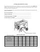
GENERATOR IDENTIFICATION For information and questions, please contact the Customer Service Help Line by calling (800) 2321195. Certain information will be requested by the Customer Service Representative and to facilitate that, please fill in the information below. Refer to the illustration below for the location of Serial Number. Record generator information in the spaces provided below.
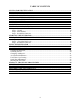
TABLE OF CONTENTS GENERATOR IDENTIFICATION ................................................................................................i SERVICE RECORD .........................................................................................................................i INTRODUCTION ............................................................................................................................1 SAFETY INFORMATION............................................................................
INTRODUCTION Thank You for Purchasing a Powerpro Technology TM Product. . This manual provides information regarding the safe operation and maintenance of this product. Every effort has been made to ensure the accuracy of the information in this manual. Powerpro Technology TM reserves the right to change this product and specifications at any time without prior notice. Please keep this manual available to all users during the entire life of the generator.
SAFETY INFORMATION Before operating this generator read and observe all warnings, cautions, and instructions on this sheet, on the generator, and in the Owner’s Manual. NOTE: The following safety information is not meant to cover all possible conditions and situations that may occur. Read the entire Owner’s Manual for safety and operating instructions. Failure to follow instructions and safety information could result in serious injury or death.
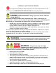
GENERAL SAFETY PROCEDURES For any questions regarding the hazard and safety notices listed in this manual or on the product, please call (800) 232-1195 M-F 8-5 CST before using the generator. DANGER: CARBON MONOXIDE. Using a generator indoors CAN KILL YOU IN MINUTES. Generator exhaust contains carbon monoxide (CO). This is a poison gas you cannot see or smell. If you can smell the generator exhaust, you are breathing CO. But even if you cannot smell the exhaust, you could be breathing CO.
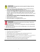
WARNING: This generator produces powerful voltage, which can result in electrocution. x x x x x x ALWAYS ground the generator before using it (see the “Ground the Generator” portion of the “GENERATOR PREPARATION” section). Generator should only be plugged into electrical devices, either directly or with an extension cord. NEVER connect to a building electrical system without a qualified electrician. Such connections must comply with local electrical laws and codes.
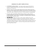
IMPORTANT SAFETY INSTRUCTIONS x SAVE THESE INSTRUCTIONS – This manual contains important instructions for Powerpro Technology 4050 generator that should be followed during installation and maintenance of the generator. x Generators vibrate in normal use. During and after the use of the generator, inspect the generator as well as extension and power supply cords connected to it for damage resulting from vibration. Have damaged items repaired or replaced as necessary.
In addition to the previous safety notices, please become familiar with the safety and hazard markings on the generator.
PACKAGE CONTENTS Your generator comes with the items listed below. Please check to see that all of the following items are included with your generator. If there are any damaged or missing items, please call (800) 232-1195 M-F 8-5 CST for customer service. DO NOT RETURN TO STORE. Store personnel are not trained to assist with damaged or missing items.
GENERATOR COMPONENTS Please familiarize yourself with the locations and functions of the various components and controls of your generator. (1)Air Cleaner- A removable, cleanable, spongelike element that limits the amount of dirt pulled into the engine. (2)Fuel Valve- Allows fuel to enter engine. (3)Fuel Filter Cup- Traps dirt and water from fuel before it enters the engine. (4)Recoil Starter- Pull-cord for starting engine. (5)Engine Switch- To start/stop engine.
ASSEMBLY Step 1 – Wheel Installation 1. Blocking up the muffler side of the generator, assemble the axle to the frame. 2. Slide the wheel and washer onto the axle, with the offset of the wheel hub against the frame. 3. Secure the wheel to the axle with the cotter pin. 4. Repeat above instructions for the remaining wheel. Step 2 –Foot Installation 1. Blocking up the engine side of the generator, assemble the rubber foot to the frame. 2. Repeat above instructions for the remaining foot.
Step 1 - Fill Oil The generator is shipped without oil. User must add the proper amount of oil before operating the generator for the first time. The oil capacity of the engine crankcase is 20 fluid oz. Select good quality detergent oil bearing the American Petroleum Institute (API) service classifications SJ, SL, or SM. (Synthetic oils may be used.) Use the SAE viscosity grade of oil from the following chart that matches the starting temperature anticipated before the next oil changes.
Step 2- Add Gasoline WARNING: This generator may emit highly flammable and explosive gasoline vapors, which can cause severe burns or even death if ignited. A nearby open flame can lead to explosion even if not directly in contact with gasoline. x x x x x x x x Do not operate near open flame. Do not smoke near generator. Always operate on a firm, level surface. Always turn generator off before refueling. Allow generator to cool for at least 2 minutes before removing fuel cap.
Step 3- Ground the Generator WARNING: Failure to properly ground the generator can result in electrocution. Ground the generator by tightening the grounding nut against a grounding wire (see figure 5). A generally acceptable grounding wire is a No. 12 AWG (American Wire Gauge) stranded copper wire. This grounding wire should be connected at the other end to a copper or brass grounding rod that is driven into the earth. Wire and grounding rod are not included in generator contents.
STARTING THE GENERATOR Before starting the generator, make sure you have read and performed the steps in the “GENERATOR PREPARATION” section of this manual. If you are unsure about how to perform any of the steps in this manual please call (800) 232-1195 M-F 8-5 CST for customer service. DANGER: CARBON MONOXIDE. Using a generator indoors CAN KILL YOU IN MINUTES. Generator exhaust contains carbon monoxide (CO). This is a poison gas you cannot see or smell.
To start your generator, perform the following steps: 1. No electrical devices should be connected to the generator during starting. Devices can make it difficult for the engine to start. 2. Check that the generator is properly grounded (see “Ground the Generator”). 3. Check the oil and fuel levels. 4. Turn the fuel valve to the “ON” position (see figure 6). 5. Move the choke lever to the “CLOSED” position (see figure 7). 6. Set the engine switch to the “ON” position. 7.
Step 1- Check the Oil Oil consumption is normal during generator usage. The generator is equipped with a low-oil shutoff to protect it from damage. The oil level in the engine should be checked before each use to ensure that the engine crankcase contains sufficient lubricant. To check or add oil, follow these steps: 1. Make sure the generator is on a level surface. Clean around oil fill. 2. Remove the oil filler/dipstick cap and check oil level. 3.
Wire Gauge) stranded copper wire. This grounding wire should be connected at the other end to a copper, brass, or steel-grounding rod that is driven into the earth. Wire and grounding rod are not included in generator contents. Grounding codes can vary by location. Contact a local electrician for area codes.
If these specifications are not available, you may estimate the Watts required by your device using the chart in figure 10. When the running wattage requirement of each electrical device has been determined, add these numbers to find the total running wattage needed. If this number exceeds the running wattage of the generator, DO NOT connect all these devices. Select a combination of electrical devices, which has a total running wattage lower than or equal to the running wattage of the generator.
1. Plug in each electrical device with the device turned off. NOTE: Be sure to attach appliances to the correct receptacles (outlets). Connect standard 120 Volt, single phase, 60 Hz loads only to the 120 Volt receptacles. Connect 120 Volt, single phase, 60Hz loads with a NEMA L5-30 plug only to the 120 Volt receptacle See Figure 11 for a depiction of each of these receptacles. 2. Push in the circuit reset buttons to the “on” position (NOTE: They may be pushed in already).
STOPPING THE GENERATOR Procedure to Stop Generator NOTE: Stopping the motor or unplugging cords from the generator while it is supplying power to devices will possibly damage the voltage regulator and result in low or no power output until the voltage regulator is replaced. Following the stopping procedure will minimize the possibility of damaged voltage regulators. 1. Turn off all electrical devices being powered by generator prior to unplugging them from the generator. 2.
MAINTENANCE / CARE Proper routine maintenance of your generator will help prolong the life of your machine. Please perform maintenance checks and operations according the schedule in figure 13. If you have questions about any of the maintenance procedures listed in this manual, please call (800) 232-1195 M-F 8-5CST. CAUTION: Never perform maintenance operations while the generator is running.
Figure 14- Checking the oil Changing/ Adding Oil Change the oil according to the maintenance schedule in figure 13. Change the oil when the engine is warm. This will allow for complete drainage. Change oil more often if operating under heavy load or high ambient temperatures. It is also necessary to drain the oil from the crankcase if it has become contaminated with water or dirt. The oil capacity of the engine in this generator is 20 fluid oz. Add oil when the oil level is low.
Air Cleaner Maintenance Routine maintenance of the air cleaner helps maintain proper air flow to the carburetor. Check that the air cleaner is free of excessive dirt. 1. 2. 3. 4. 5. Unhinge the clasps at the top and bottom of the air cleaner cover (see figure 17). Remove the sponge-like elements from the cover. Wipe the dirt from inside the empty air cleaner cover. Wash the sponge-like elements in household detergent and warm water. Allow to dry.
Spark Plug Maintenance The spark plug is important for proper engine operation. A good spark plug should be intact, free of deposits, and properly gapped. To inspect the spark plug: 1. Pull on the spark plug cap to remove it. 2. Unscrew the spark plug from the generator using the spark plug wrench included with this product (see figure 19). 3. Visually inspect the spark plug. If it is cracked or chipped, discard and replace with a new spark plug. 4. Measure the plug gap with a gauge (see figure 20).
STORAGE / TRANSPORT PROCEDURES CAUTION: Never place any type of storage cover on the generator while it is still hot. If the generator is being stored for short periods of time (30 – 60 days), add stabilized fuel to the fuel tank until full. NOTE: Filling the tank reduces the amount of air in the tank and helps reduce deterioration of fuel. Run the engine for 2 – 3 minutes allowing stabilized fuel mixture to circulate through the carburetor.
SPECIFICATIONS Generator Running Wattage 3250 W Starting Wattage Rated Voltage 4050W 120 V Rated Amperage 27A Rated Frequency 60 Hz Phase Single Dimensions(in) (without mobility kit) Weight length= 23.3 width= 18.3 height= 18 114 lbs Engine Engine type Ignition system 4-stroke OHV single cylinder with forced air cooling system non-contact transistor 212 cm3 Displacement Fuel tank capacity 12 L (3.1 US gal.) Oil capacity 0.6 L (20 fl oz.
TROUBLESHOOTING IMPORTANT: If trouble persists please call our customer help line at (800) 232-1195 M-F 8-5 Central Time. Problem Cause Solution Engine switch is set Set engine switch to "ON". to "OFF". Fuel valve is turned to "OFF". Turn fuel valve to "ON" position. Choke is open. Close the choke. Engine will not start Engine is out of fuel. Engine is filled with contaminated or old gasoline. Spark plug is dirty. Spark plug is broken. Generator is not on level surface. Oil is low Air cleaner is dirty.
ENGINE EXPLODED VIEW AND PARTS LIST 27
ITEM DESCRIPTION 1 2 3 4 5 6 7 8 9 10 11 12 13 14 15 16 17 18 19 20 21 22 23 24 25 26 27 28 29 30 31 32 33 34 35 36 37 38 39 40 41 42 43 44 45 46 47 48 49 50 51 52 53 54 55 ITEM DESCRIPTION CYLINDER HEAD ASSEMBLY CYLINDER HEAD SUBASSEMBLY IN VALVE GUIDE EX VALVE GUIDE VALVE GUIDE CIRCLIP INTAKE STUD EXHAUST STUD CYLINDER HEAD GASKET CYLINDER HEAD COVER CYLINDER HEAD COVER GASKET BREATHER TUBE BOLT PIN CYLINDER HEAD BOLT SPARK PLUG CRANKCASE ASSEMBLY OIL SENSOR GOVERNOR GEAR ASSEMBLY WASHER GOVERNOR GEAR W
ITEM DESCRIPTION 111 112 113 114 115 116 117 118 119 120 121 123 124 125 126 127 FLOAT GASKET AIR CLEANER ASSEMBLY ELEMENT ASSEMBLY ELEMENT 1 ELEMENT 2 AIR CLEANER COVER BOLT AIR CLEANER ELEMENT BRACKET AIR CLEANER ELEMENT GASKET AIR CLEANER BASE NUT FLYWHEEL NUT STARTER PULLEY FLYWHEEL FAN IGNITION COIL ASSEMBLY SPARK PLUG CAP 29 ITEM DESCRIPTION 128 129 130 131 132 133 134 135 136 137 138 139 140 141 BOLT STOP ENGINE WIRE REGULATING ARM NUT REGULATING BOLT GOVERNOR SPRING GOVERNOR ROD SMALL GOVERNOR S
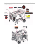
GENERATOR EXLODED VIEW AND PARTS LIST 30
ITEM DESCRIPTION 1 2 3 4 5 6 7 8 9 10 11 12 13 14 15 16 17 18 19 20 21 22 23 24 25 26 27 28 29 30 31 32 33 34 35 36 37 38 39 ITEM DESCRIPTION ENGINE ASSEMBLY MUFFLER ASSEMBLY MUFFLER GUIDE BOLT BOLT BRACKET BOLT EXHAUST OUTLET GASKET BOLT EXHAUST PIPE NUT FUEL TANK FUEL FILTER FUEL CAP FUEL TANK RUBBER BUSH WASHER BOLT FUEL GAUGE ASSEMBLY FUEL GAUGE GASKET FUEL GAUGE PLATE FUEL COCK ASSEMBLY TUBE CLIP FUEL TUBE SCREW AXLE ASSEMBLY AXLE AXLE BRACKET WASHER NUT SCREW WHEEL WASHER COTTER PIN WHEEL ASSEMBLY F
WIRING DIAGRAM 32
NOTES: 33
WARRANTY STATEMENT FOR POWERPRO TECHNOLOGY PRODUCTS PowerPro Technology™ generators are warranted (to the original purchaser) to be free from defects in materials and workmanship for a period of two (2) years from the date of original purchase. Generators used for commercial or for rental have a warranty period of 90 days from date of original purchase. Please fill out the enclosed warranty card and mail it to Power Pro Technology along with a copy of the receipt.