MODEL 6510, 6510T OSCILLATING SPINDLE SANDER For replacement parts visit WENPRODUCTS.COM 226766 IMPORTANT: Your new tool has been engineered and manufactured to WEN’s highest standards for dependability, ease of operation, and operator safety. When properly cared for, this product will supply you years of rugged, trouble-free performance. Pay close attention to the rules for safe operation, warnings, and cautions.
TABLE OF CONTENTS Specifications................................................................................... 2 Introduction..................................................................................... 3 General Safety Rules........................................................................ 4 Specific Safety Rules for the Spindle Sander.................................... 6 Electrical Information.......................................................................
INTRODUCTION Thanks for purchasing the WEN Spindle Sander. We know you are excited to put your tool to work, but first, please take a moment to read through the manual. Safe operation of this tool requires that you read and understand this operator’s manual and all the labels affixed to the tool. This manual provides information regarding potential safety concerns, as well as helpful assembly and operating instructions for your tool. SAFETY ALERT SYMBOL: Indicates danger, warning, or caution.
GENERAL SAFETY RULES Safety is a combination of common sense, staying alert and knowing how your item works. SAVE THESE SAFETY INSTRUCTIONS. WARNING: Read and understand all warnings, cautions and operating instructions before using this tool. Failure to follow all instructions listed below may result in personal injury and tool damage. WORK AREA SAFETY 1. Keep work area clean and well lit. Cluttered or dark areas invite accidents. 2.
GENERAL SAFETY RULES 4. Prevent unintentional starting. Ensure the switch is in the off-position before connecting to power source and/or battery pack, picking up or carrying the tool. Carrying power tools with your finger on the switch or energizing power tools that have the switch on invites accidents. 5. Remove any adjusting key or wrench before turning the power tool on. A wrench or a key left attached to a rotating part of the power tool may result in personal injury. 6. Do not overreach.
SPECIFIC RULES FOR THE SPINDLE SANDER WARNING: Do not let comfort or familiarity with the product replace strict adherence to product safety rules. Failure to follow the safety instructions may result in serious personal injury. 1. TOOL PURPOSE. This sander is designed to sand wood or wood-like products only. Sanding or grinding other materials could result in fire, injury, or damage to the workpiece.
SPECIFIC RULES FOR THE SPINDLE SANDER 11. FEEDING THE WORKPIECE. • Allow spindle to reach full speed before feeding the workpiece. Do not turn on the machine while the sanding sleeve is contacting the workpiece. • Be aware of the direction of the spindle’s rotation (counterclockwise). Only feed the workpiece AGAINST the rotation of the spindle. • Firmly hold the workpiece and lightly ease it against the spindle. Do not forcefully jam a workpiece into the sanding surface. 12. DO NOT TOUCH MOVING PIECES.
ELECTRICAL INFORMATION DOUBLE-INSULATED TOOLS The tool’s electrical system is double insulated where two systems of insulation are provided. This eliminates the need for the usual three-wire grounded power cord. Double insulated tools do not need to be grounded, nor should a means for grounding be added to the product. All exposed metal parts are isolated from the internal metal motor components with protecting insulation.
KNOW YOUR SPINDLE SANDER UNPACKING With the help of a friend or trustworthy foe, carefully remove the sander from the packaging. Make sure to take out all contents and accessories. Do not discard the packaging until the sander is completely assembled. TOOL PURPOSE Spindle sanding is the preferred method of removing material from inside curves and irregular edges. The oscillating spindle moves up and down as it rotates to help smooth workpiece surfaces quickly and evenly.
ASSEMBLY & ADJUSTMENTS Before using the spindle sander, you must configure the machine by installing the appropriate sanding drum, sanding sleeve, throat plate and spindle washer for your operation. Check your packing list against the diagram below. If any part is damaged or missing, please contact our customer service at (800) 232-1195, M-F 8-5 CST or email us at techsupport@wenproducts.com. PACKING LIST 1/2"/ .5" 3/4"/ .75" 1" 1-1/2"/ 1.
ASSEMBLY & ADJUSTMENTS WARNING: Do not plug in or turn on the tool until it is fully assembled according to the instruc- tions. Failure to follow the safety instructions may result in serious personal injury. ACCESSORY SELECTION Refer to the packing list diagram on page 10 to ensure that you are using the proper sizes of throat plates, drums and washers for each respective sanding sleeve.
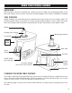
ASSEMBLY & ADJUSTMENTS WARNING: Do not plug in or turn on the tool until it is fully assembled according to the instruc- tions. Failure to follow the safety instructions may result in serious personal injury. MACHINE MOUNTING For safe operation, the machine must be secured onto a flat, secure workbench or stand. The base of the machine has four 6 mm mounting holes. Place the sander on the mounting surface, and insert a pencil through the mounting holes to mark the hole locations.
OPERATION ON/OFF SWITCH WITH SAFETY KEY The keyed ON/OFF switch (Fig. 4) is intended to prevent unauthorized use of the sander. Fig. 3 ON 1. To turn the sander ON, insert the safety key into the key slot in the center of the switch. Lift the switch up to turn ON the sander. OFF 3. To turn the sander OFF, push switch down. Remove the safety key when the sander has come to a complete stop by gently pulling it out. WARNING: Remove the safety key whenever the sander is not in use.
MAINTENANCE WARNING: To avoid accidents, turn OFF and unplug the tool from the electrical outlet before cleaning, adjusting, or performing any maintenance or lubrication work. WARNING: Any attempt to repair or replace electrical parts on this tool may be hazardous. Servicing of the tool must be performed by a qualified technician. When servicing, use only identical WEN replacement parts. Use of other parts may be hazardous or induce product failure.
TROUBLESHOOTING GUIDE WARNING: Stop using the tool immediately if any of the following problems occur. Repairs and replacements should only be performed by an authorized technician. For any questions, please contact our customer service at (800) 232-1195, M-F 8-5 CST or email us at techsupport@wenproducts.com. PROBLEM CAUSE SOLUTION Sander does not turn on 1. Power cord or extension cord damaged or not properly plugged in. 2. Safety key is removed from power switch. 3.
TROUBLESHOOTING GUIDE WARNING: Stop using the tool immediately if any of the following problems occur. Repairs and replacements should only be performed by an authorized technician. For any questions, please contact our customer service at (800) 232-1195, M-F 8-5 CST or email us at techsupport@wenproducts.com. PROBLEM CAUSE 1. Using a sanding grit that is too fine. 2. Using too much pressure. 3. Work held still for too long. 4. Sanding sleeve loaded with debris. 1. Use a coarser-grit sanding accessory.
EXPLODED VIEW & PARTS LIST 102 103 104 105 106 107 108 109 110 96 97 98 99 5 (96, 97, 98, 99, 100, 101) 3 (102, 103, 104, 105, 106, 107) 15 2 (113, 114, 115) 18 1 " 9 10 11 12 17 16 66 8 76 6 75 74 79 80 117 118 21 22 23 71 72 69 70 67 68 24 25 28 29 34 39 40 85 93 94 73 87 88 86 20 27 36 119 19 26 35 81 89 90 91 92 101 14 7 83 100 112 13 4 (108, 109, 110, 111, 112) 82 111 116 30 31 32 33 37 38 41 42 43 44 45 46 47 48 49 50 51 52 53 54 55 56 57 59 60 58 6
EXPLODED VIEW & PARTS LIST 18 No. Part No. Description Qty. No. Part No. Description Qty.
EXPLODED VIEW & PARTS LIST No. Part No. Description Qty. No. Part No. Description Qty. 64 90225-064 Rubber Washer 1 97 90225-097 3/4" Throat Plate 1 65 90225-065 Felt 1 98 90225-098 1" Throat Plate 1 66 90225-066 Wheel Support 1 99 90225-099 1-1/2" Throat Plate 1 67 90225-067 Wire Assembly 1 1 100 90225-100 2" Throat Plate 1 68 90225-068 Wire Assembly 2 1 101 90225-101 1 69 90225-069 Rectifier 1 70 90225-070 Screw 4.
WARRANTY STATEMENT WEN Products is committed to building tools that are dependable for years. Our warranties are consistent with this commitment and our dedication to quality. LIMITED WARRANTY OF WEN CONSUMER POWER TOOLS PRODUCTS FOR HOME USE GREAT LAKES TECHNOLOGIES, LLC (“Seller”) warrants to the original purchaser only, that all WEN consumer power tools will be free from defects in material or workmanship for a period of two (2) years from date of purchase.