
Use and Care Manual


MAINTENANCE
13
Figure 9
Figure 11
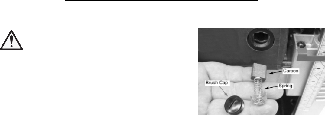
BRUSH INSPECTION AND REPLACEMENT
WARNING: Turn planer off and disconnect from power
source before inspecting or replacing brushes.
Brush life depends on amount of load on motor. Regularly
inspect brushes after 100 hours of use. Brushes are located on either
side of planer motor, on both the front and rear side of the planer.
• Loosen brush cap and carefully remove brush from motor.
• Replace brushes if spring is damaged.
• Replace brushes if carbon is worn.
• Tighten brush caps after replacement.
Figure 12
ADJUSTING TABLE LEVEL
Refer to Exploded Views, Figures 13 and 14, pages 15 and 17.
The planer will produce uneven depth of cut (tapered cut) if the rollercase (26 - Figure 14) is not parallel with the
base (20 - Figure 13). To restore parallelism of the rollercase with the base:
• Using a test piece, measure the height of the taper.
• Turn planer off and disconnect from power source.
• Fold the front and rear extension tables.
• Lay planer carefully on it’s side so that bottom side of the base is exposed.
• Clamp vise plier (not supplied) on the left side of shaft (31 - Figure 13) next to the gear (35 - Figure 13).
• Remove retaining ring (34 - Figure 13) and disengage right gear from the elevation screw gear.
• Slowly rotate handle (5 - Figure 13) to raise or lower rollercase. Rollercase will move by 0.006" with every turn
of the gear by one tooth. Move rollercase to the required distance to offset the taper.
• Re-engage the right and elevation screw gear and replace retaining ring to secure.
• Release and remove vise plier.
• Set the planer back on its base.
• Make a test cut to verify adjustment.
REPLACING V-BELT
Refer to Exploded Views, Figures 13 and 14, pages 15 and 17.
Inadequate tension in the V-belt (46 - Figure 14) will cause the belt to slip from the motor pulley (49 - Figure 14)
or drive pulley (47 - Figure 14). Loose belts must be replaced. To replace V-belt:
• Turn planer off and unplug from power source.
• Loosen and remove screws (1 - Figure 13) on right cap (6 - Figure 13). Remove panel (37 - Figure 13).
• Loosen and remove screws (29 - Figure 14) on belt guard (30 - Figure 14). Remove belt guard.
• Loosen bolt (38 - Figure 14) to loosen motor assembly.
• Remove old belt by walking the belt from motor and drive pulleys alternatively. Push motor down and pull the
belt outward while turning the pulleys at the same time.
• Replace with new belt. Walk the belt on to the pulleys in the reverse manner as when removing the belt.
• Make sure the belt is evenly seated all the way on the motor and drive pulley grooves.
• Pry motor upward to apply tension to belt. Secure in position by tightening bolt (38 - Figure 14).
• Replace belt guard and screws (29, 30 - Figure 14).
• Replace and secure right panel.