
Use and Care Manual


88
ASSEMBLY AND ADJUSTMENTS
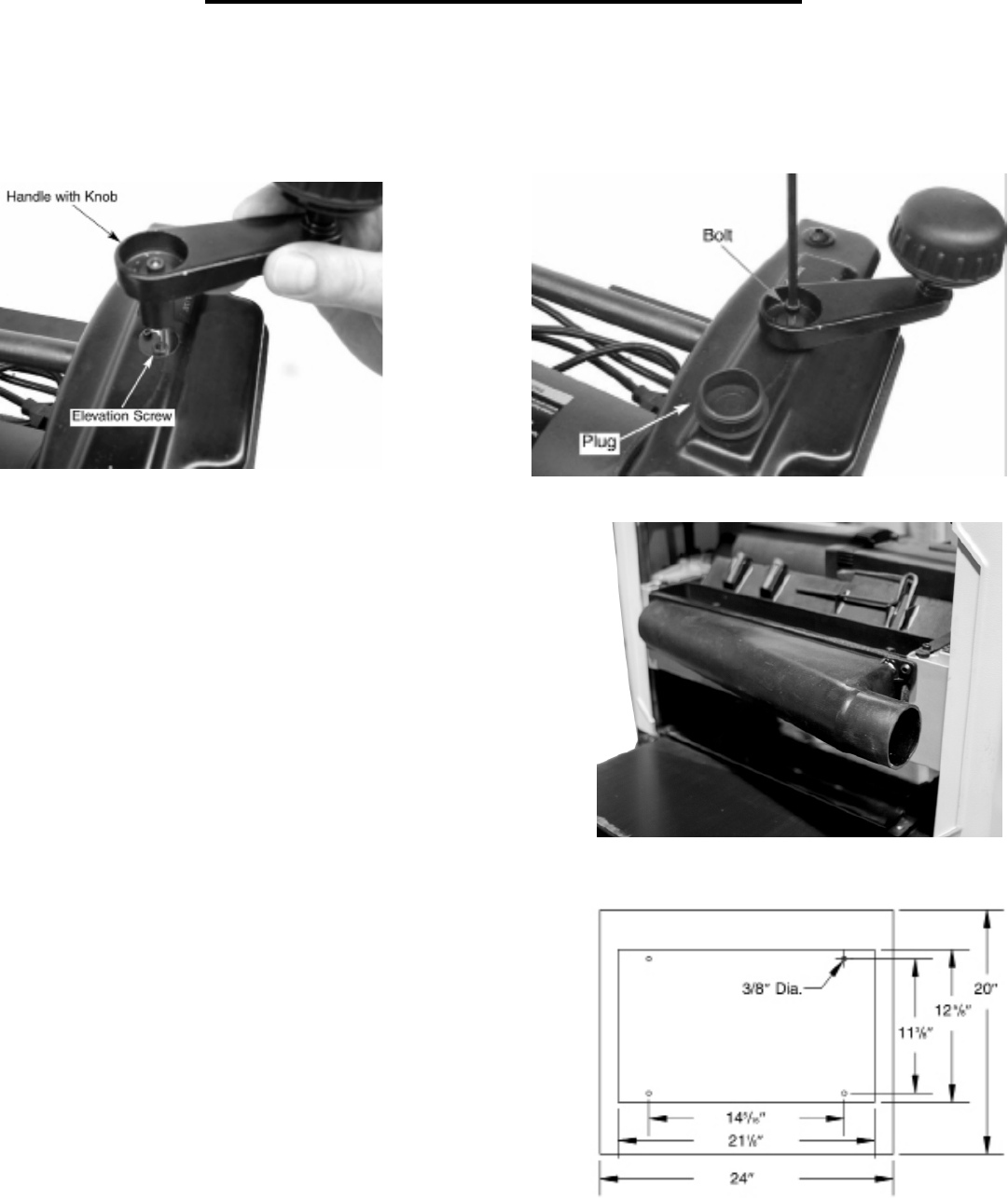
INSTALL DEPTH ADJUSTING HANDLE (FIGURE 2 & 3)
The handle and knob should be installed to top-right of the planer. Insert the handle with the knob onto the
elevation screw’s top. Secure handle with bolt using T-handle wrench provided. Insert plug into handle to cover
bolt.
Figure 2
Figure 3
ATTACH DUST CHUTE (FIGURE 4)
Planer is best used along with a dust collector. Dust chute is
included. The dust chute is mounted to the rollercase using two
thumb screws. The dust chute can be mounted to direct chips to
either side of planer.
After mounting, connect wet/dry vacuum hose to dust chute. Be
sure to turn the vacuum on before operating the planer.
Figure 4
MOUNT PLANER TO WORK SURFACE (Figure 5)
The planer is designed to be portable so it can be moved to a
job site. However, it should always be mounted to a stable, level
bench or table in a place with ample lighting and correct power
supply. Make sure there is plenty of room for moving the work-
piece through the entire cut. Neither the operators or the bystand-
ers should have to stand in line with the wood while using the tool.
The base of the planer has four mounting holes. Mount the plan-
er to the workbench or to the tool stand using bolts, flat washers
and hex nuts (not supplied). Figure 5 shows the base dimensions,
mounting holes and required space to allow for table assembly.
Securely mount the planer to the work table by bolting it through
the holes. Make sure the planer does not rock and that the work
table is level.
Figure 5