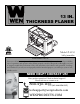
3 IN. THICKNESS PLANER Model # 6552 bit.ly/wenvideo 4005911 IMPORTANT: Your new tool has been engineered and manufactured to WEN’s highest standards for dependability, ease of operation, and operator safety. When properly cared for, this product will supply you years of rugged, trouble-free performance. Pay close attention to the rules for safe operation, warnings, and cautions. If you use your tool properly and for intended purpose, you will enjoy years of safe, reliable service.
TABLE OF CONTENTS Technical Data General Safety Rules Specific Safety Rules For Planer Electrical Information Know Your Planer Assembly and Adjustments Operation Maintenance Troubleshooting Exploded View and Parts List Warranty 2 3 4 5 7 7 10 14 15 16 18 TECHNICAL DATA 6552 Model Number: 120 V, 60 Hz, 15A Motor: 8500 RPM Cutterhead Speed: 3 blades Number of Blades 25500 cuts per minute Cuts Per Minute: 26 FPM Feed rate: 3/32˝ Max. Depth of Cut (for boards 6 inches or less): 1/32˝ Max.
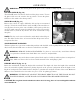
GENERAL SAFETY RULES Safety is a combination of common sense, staying alert and knowing how your item works. SAVE THESE SAFETY INSTRUCTIONS. WARNING: To avoid mistakes and serious injury, do not plug in your tool until the following steps have been read and understood. 1. READ and become familiar with this entire instruction manual. LEARN the tool’s applications, limitations, and possible hazards. 2. AVOID DANGEROUS CONDITIONS. Do not use power tools in wet or damp areas or expose them to rain.
GENERAL SAFETY RULES 15. DO NOT OVERREACH. Keep proper footing and balance at all times. Wear oil-resistant rubber-soled footwear. Keep the floor clear of oil, scrap, and other debris. 16. MAINTAIN TOOLS PROPERLY. ALWAYS keep tools clean and in good working order. Follow instructions for lubricating and changing accessories. 17. CHECK FOR DAMAGED PARTS. Check for alignment of moving parts, jamming, breakage, improper mounting, or any other conditions that may affect the tool’s operation.
SPECIFIC RULES FOR THE PLANER 7. Keep hands clear of all moving parts. 8. Do not force cut. Slowing or stalling will overheat motor. Allow automatic feed to function properly. 9. Use quality lumber. Blades last longer and cuts are smoother with good quality wood. 10. Do not plane material shorter than 15”, narrower than 3/4”, wider than 13” or thinner than 1/2”. 11. Never make planing cut deeper than 3/32". 12. For workpieces longer than 24", use material support stands. 13.
ELECTRICAL INFORMATION WARNING: This tool is for indoor use only. Do not expose to rain or use in damp locations. Guidelines for using extension cords Make sure your extension cord is in good condition. When using an extension cord, be sure to use one heavy enough to carry the current your product will draw. An undersized cord will cause a drop in line voltage resulting in loss of power and overheating. The table below shows the correct size to be used according to cord length and nameplate ampere rating.
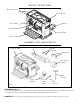
KNOW YOUR PLANER Roller Extensions Crank Handle Power Switch Dust Port Circuit Breaker Carrying Handle Infeed Table ASSEMBLY AND ADJUSTMENTS Thickness Planer Dust Chute Thumb Screw (x2) Magnet (x2) Dust Chute Adapter Hex Wrench Crank Handle Fig. 1 Socket Head Bolt Flat Washer UNPACKING (Fig. 1) The body of the planer comes assembled as one unit. All additional parts pictured above should be located and accounted for before assembling. Do not discard the packaging until you have done so.
ASSEMBLY AND ADJUSTMENTS 1 ATTACHING THE CRANK HANDLE (Fig. 2) It’s time to put this thing together! First, place the washer (Fig. 2 - 3) over the socket head bolt (Fig. 2 - 2) and feed the bolt into the handle (Fig. 2 - 4). Tighten the bolt to secure the handle in position on top of the planer. Place the handle cap (Fig. 2 - 1) onto the handle as shown in Fig. 2. 2 3 4 Fig. 2 PREPARING THE TABLES (Fig. 3 - 6) Lower the infeed and outfeed tables. Fig. 3 Fig.
ASSEMBLY AND ADJUSTMENTS ATTACH DUST CHUTE (Fig. 7) Thickness planers are best used with the aid of a dust collector. To install the dust chute, simply mount it to the rollercase using the two thumb screws (Fig. 7 - 1). The dust chute can be mounted in either direction to direct the flow of chips to either side of planer. 1 After mounting, connect wet/dry vacuum hose Fig. 7 to dust chute. Be sure to turn the vacuum on before operating the planer.
OPERATION WARNING: Do not connect planer to the power source until all assembly steps have been completed. ON/OFF SWITCH (Fig. 10) The ON/OFF switch is located on the front of the planer motor. To turn the planer ON, move the switch to the up position. To turn the planer OFF, move the switch to the down position. SWITCH LOCK (Fig. 11) Remove the red tab to engage child-safety lock and prevent unwanted start-ups.
OPERATION DEPTH OF CUT (Fig. 12 - 1) Two small 1/16-inch lips have been added to either side of the front of the planer. This is in order to decrease the maximum cutting depth from 3/32 of an inch to 1/32 of an inch for boards over 6 inches wide. Of course, this planer could handle the removal of 3/32 of an inch on 13-inch wide boards. However, not only will this shorten the lifespan of the motor and the cutting blades, but also will not provide the best finish to the board.
re cti on of G Di THE DO’S AND DONT’S OF GRAIN DIRECTION It is important that the cutterhead always cuts in the same direction as the grain. There are six sides to every board: two face grains, two side/edge grains, and two end grains. Never plane with the end grain facing upwards. Only plane side and face grains. Otherwise, the board has a chance of splintering and exploding inside of the planer. rai n OPERATION When planing side and face grain, always plane in the direction of the grain.
OPERATION AVOIDING SNIPE Thickness planers tend to leave a small bit of snipe at the end of the planed boards, particularly for longer workpieces. Snipe is a small dip that occurs from the weight of the board tilting downwards, thus pushing the other end of the board into the cutter head, creating an uneven finish. Snipe will occur when boards are not supported properly or when only one feed roller is in contact with the work at beginning or end of cut.
MAINTENANCE CHECK FOR WORN BLADES Condition of blades will affect the precision of cuts. Observe the quality of the cut that the planer produces to check the condition of the blades. Dull blades will tear, rather than sever wood fibers and produce fuzzy appearances. Raised grain will occur when dull blades pound on wood that has varying density. Raised edges will also be produced where the blades have been nicked.
MAINTENANCE WARNING: Turn planer off and disconnect from power source before performing any maintenance. BRUSH INSPECTION AND REPLACEMENT (Fig. 16) Brush life depends on the load of the motor. Regularly inspect brushes after 100 hours of use. Brushes are located on either side of the planer motor, on both the front and rear side of the planer. Loosen brush cap and carefully remove brush from motor. Replace brushes if the spring is damaged. Replace brushes if the carbon is worn.
EXPLODED VIEW AND PARTS LIST 16
EXPLODED VIEW AND PARTS LIST No. Part No. Description Qty 1 Handle Assembly 1 2 Cap 3 6550-105 4 No. Part No. Description Qty 48 6552-048 Pan Head Screw 3 1 49 6552-049 Cutterhead Pulley 1 Socket Head Screw 1 50 6552-050 Motor Pulley 1 Flat Washer 1 51 6550-246 Belt No. Part No.
LIMITED TWO YEAR WARRANTY WEN Products is committed to building tools that are dependable for years. Our warranties are consistent with this commitment and our dedication to quality. LIMITED WARRANTY OF WEN CONSUMER POWER TOOLS PRODUCTS FOR HOME USE GREAT LAKES TECHNOLOGIES, LLC (“Seller”) warrants to the original purchaser only, that all WEN consumer power tools will be free from defects in material or workmanship for a period of two (2) years from date of purchase.