0-INCH DRUM SANDER Model # 65910 For replacement parts visit WENPRODUCTS.COM bit.ly/wenvideo IMPORTANT: Your new tool has been engineered and manufactured to WEN’s highest standards for dependability, ease of operation, and operator safety. When properly cared for, this product will supply you years of rugged, trouble-free performance. Pay close attention to the rules for safe operation, warnings, and cautions.
TABLE OF CONTENTS Technical Data Safety Introduction General Safety Rules Electrical Information Specific Rules for Drum Sanders Know Your Drum Sander Unpacking Assembly Preparation Operation Adjustments Maintenance Troubleshooting Exploded View and Parts List Warranty Statement 2 3 4 6 7 8 9 10 14 18 19 22 24 26 30 TECHNICAL DATA Model Number: Motor: Drum Speed: Sandpaper Speed: Conveyor Feed Speed: Maximum Workpiece Width: Minimum Workpiece Width: Maximum Workpiece Height: Minimum Workpiece Height: Mini
SAFETY INTRODUCTION Hello! Thank you for purchasing the WEN Drum Sander. Safe operation of this power tool requires that you read and understand this operator’s manual and all labels affixed to the tool. Safety is a combination of common sense, staying alert, and knowing how your tool works. The purpose of the following safety symbol is to attract your attention to possible dangers. We don’t want any of our beloved WEN customers accidentally injuring themselves.
GENERAL SAFETY RULES Safety is a combination of common sense, staying alert and knowing how your item works. SAVE THESE SAFETY INSTRUCTIONS. WARNING! Read all safety warnings and all instructions. Failure to follow the warnings and instructions may result in electric shock, fire and serious injury. To avoid mistakes and serious injury, do not plug in your tool until the following steps have been read and understood. WORK AREA SAFETY 1. Keep work area clean and well lit.
GENERAL SAFETY RULES POWER TOOL USE AND CARE 1. Avoid accidental start-ups. Make sure the power switch is in the OFF position before connecting the plug to a power source or carrying the tool. 2. Check power tool for damaged parts. Check for misalignment of moving parts, jamming, breakage, improper mounting, or any other conditions that may affect the tool’s operation. Do not use the power tool if the switch does not turn ON/OFF. Any part that is damaged should be properly repaired or replaced before use.
ELECTRICAL INFORMATION GROUNDING INSTRUCTIONS IN THE EVENT OF A MALFUNCTION OR BREAKDOWN, grounding provides the path of least resistance for an electric current and reduces the risk of electric shock. This tool is equipped with an electric cord that has an equipment grounding conductor and a grounding plug. The plug MUST be plugged into a matching outlet that is properly installed and grounded in accordance with ALL local codes and ordinances. DO NOT MODIFY THE PLUG PROVIDED.
SPECIFIC RULES FOR DRUM SANDERS 1. INSPECT THE TOOL. Before operation, check the tool for any damage or missing parts. Make sure all adjustments are correct and all connections are tight. Do not use the tool if any part is missing or damaged. Check the conveyor belt to make sure there is no debris or sawdust between components. Never sand with the sanding drum cover open or safety guards removed. 2. PERSONAL SAFETY.
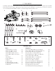
KNOW YOUR DRUM SANDER Use the diagram below to become familiarized with the components and controls of your drum sander. If you have any questions or concerns, please contact our Customer Service at (800) 232-1195, M-F 8-5 CST or email us at techsupport@wenproducts.com.
UNPACKING Carefully unpack all items from the box. Do not discard the packaging until the machine is completely assembled. Check all parts and compare against the list below. If any part is damaged or missing, please contact our customer service at (800) 232-1195, M-F 8-5 CST or email techsupport@wenproducts.com. 1 6 2 3 4 5 7 8 11 S1 S3 S5 S2 S4 S6 9 12 S7 10 13 S8 S10 S12 S9 S11 S13 S14 PACKING LIST Parts 1. Drum Sander Assembly 2. Short Top Brace 14-5/8" 3.
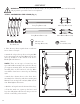
ASSEMBLY WARNING: To avoid injury from accidental startups, do not plug in the drum sander until all assembly and preparation procedures have been completed. STEP 1: ASSEMBLING THE STAND (Fig. 1) Legs (x2) Feet Pads (x4) Long Top Braces (x2) Short Top Braces (x2) Long Bottom Braces (x2) Short Bottom Braces (x2) M8-1.25 x 12 Carriage Bolts (x32) M8-1.25 Lock Nuts (x32) 1. Place the 4 top braces upside down on a flat surface to form a rectangle.
ASSEMBLY STEP 2: INSTALLING THE WHEELS (Fig. 2) Wheel Brackets (x2) Wheels (x2) M8-1.25 x 16 Hex Bolts (x4) Wheel Axle (x1) M8-1.25 Lock Nuts (x4) Cotter Pins 4 x 20mm (x2) 1. Attach the 2 wheel brackets to the 2 wheelmounting legs with (4) M8-1.25 x 16 hex bolts and (4) M8-1.25 lock nuts. Note that the left and right wheel brackets are different configurations. Tighten the fasteners with a wrench. 2. Slide the wheel axle through the 2 wheel brackets.
ASSEMBLY STEP 4: MOUNTING THE MACHINE ONTO THE STAND (Fig. 4) M10-1.5 x 30 Hex Bolts (x4) 10mm Flat Washers (x4) M10-1.5 x 30 Hex Nut (x4) Drum Sander Assembly (x1) 1. This sander weighs over 150 lbs, so you will need a strong muscular friend (or a trustworthy foe) to help you lift it up. Carefully place the sander onto the assembled stand in the orientation you prefer (the motor side of the sander can be positioned above the wheels side or the handles side). 2.
ASSEMBLY STEP 6: MOUNTING THE DUST PORT (Fig. 6) WARNING: Sanding produces a lot of dust that could be harmful to your health. Always operate using a dust collection system and approved face mask to minimize the risk of lung damage from dust inhalation. DO NOT operate the drum sander without an adequate dust collection system. Dust hose and hose clamp (x1) (not included) Dust Port (x1) 1. Install the dust port onto the drum cover. 2.
SANDPAPER INSTALLATION SANDPAPER PREPARATION Sandpaper for drum sanders are trimmed specifically to properly wrap around the sanding drum. You can find precut drum sander sandpaper that is ready to use and requires no measuring or trimming. You can also purchase a 3-1/4 inch (82mm) wide sandpaper roll and trim it using the chart below or your existing sandpaper as a template. 62-1/2″ (1585mm) 1/8″ (3.
PREPARATION To install new sandpaper (Fig. 9 - 12): 1. Roll the sanding drum until the slot on the left of the drum is on top. Reach under the left lip of the drum to locate the spring clamp. 2. Lift the clamping device and insert the end of the replacement sandpaper into the slot (Fig. 9). Push the sandpaper so that about 1 inch of sandpaper is loaded to ensure enough grip. Align the left side of the sandpaper with the left lip on the drum. Fig. 9 3.
PREPARATION WARNING: To avoid injury from accidental startups, always ensure that the tool is switched OFF and unplugged from the power supply before making adjustments. INTRODUCTION The drum sander is a machine designed to sand wooden workpieces to a desired thickness and smoothness. Before adjusting and operating the machine, it is important to know that drum sanding is different from thickness planing. Drum sanding can only remove material in increments of 1/32 inch (0.
PREPARATION ADJUSTING THE DEPTH OF CUT (Fig. 13) The depth of cut of your drum sander is the amount of material that is removed by the sanding drum in one pass. The proper depth of cut depends on many variables, including the feed rate, hardness of the material and width of the material. For a smoother result, a smaller depth of cut is always recommended. IMPORTANT: You should never remove more than 1/32 inch (0.8mm) of material in one pass.
OPERATION WARNING: Do not attempt to plug in or operate your tool until the entire operator’s manual has been read and understood. Make sure that the machine is assembled and setup properly. Failure to do so could result in personal injury and damage to the tool. WARNING: Loose hair, clothing, or jewelry could get caught in machinery and cause serious personal injury. Keep these items away from moving parts at all times to reduce the risk of injury.
ADJUSTMENTS WARNING: To avoid injury from accidental startups, always ensure that the tool is switched OFF and unplugged from the power supply before making adjustments. The following settings should be correctly adjusted from the factory. However, they may need to be checked and adjusted to ensure optimal sanding performance. Refer to the sections below to adjust the following settings.
ADJUSTMENTS HEIGHT ADJUSTMENT TENSION SCREWS (Fig. 16 & 17) The six height adjustment tension screws on the height adjustment wheel side of the sander apply pressure to the sliding mechanism of the sanding head. The tightness of the screws can be tuned to allow accurate and smooth height adjustments. 1 If the screws are too loose, the drum will deflect during operation, causing an uneven sanded surface.
ADJUSTMENTS ADJUSTING THE PRESSURE ROLLER (Fig. 20 & 21) There are two pressure rollers (Fig. 20 - 1) on each side of the sanding drum. The rollers extrude slightly below the bottom of the drum in order to press the workpiece against the conveyor belt as it passes through the sander. The pressure on the rollers is controlled by the springs and adjustment screws that can be accessed from the inside of the drum housing. If the roller pressure is too high, kickback and snipe may occur.
MAINTENANCE WARNING: To prevent serious injury from accidental operation, always turn off and disconnect the machine from power source before installation, cleaning and maintenance operations. WARNING: Use caution when performing maintenance on the drum sander. Do not wear long sleeve shirts, neckties or jewelry. Make sure to tie back long hair. DAILY INSPECTION For optimum performance, inspect the machine before every use. Check the following before each operation.
MAINTENANCE CONVEYOR FEED BELT REPLACEMENT (Fig. 24 & 25) Regularly check the conveyor belt before operation. The conveyor belt may need replacement due to normal wear and tear, contact with the sanding drum abrasive during operation, mis-tracking of the conveyor belt, or excessive build-up. Follow the steps below to remove and replace the conveyor belt. 1. Turn off and disconnect the machine from the power source. 2.
TROUBLESHOOTING WARNING: Stop using the tool immediately if any of the following problems occur or risk serious personal injury. Repairs and replacements should only be performed by authorized personnel. If you have any questions, please contact our customer service at (800) 232-1195, M-F 8-5 CST. Problem Common Causes Machine does not start 1. Safety key removed from switch. 2. The power cord damaged or not properly plugged in. 3. Faulty capacitor. 4. Motor overloaded and circuit breaker trips. 5.
TROUBLESHOOTING Problem Workpiece slips on conveyor. Common Causes 1. Conveyor belt dirty or worn. 2. Pressure rollers not properly adjusted. Solution 1. Clean/replace conveyor belt (see page 21). 2. Properly adjust pressure roller (see page 20). 1. Height lock knob not tight and sanding drum is deflecting up. Uneven 2. Conveyor belt not parallel to sanding workpiece drum. thickness from 3. Height adjustment tension screws are side to side. too loose. 4. Conveyor belt is worn. 1.
SECTION EXPLODED VIEW 9: AND PARTS PARTS LIST STAND 1 Stand 3 4 2 19 11 6 14 5 13 19 18 29 28 17 7 19 15 27 28 27 19 17 21 22 6 8 20 9 26 1 2 4 6 16 3 5 12 12 19 17 10 15 9 DESCRIPTION 1 No.P0716001 Part No.HANDLE GRIP Description 2 1 P0716002 HANDLE Handle Grip 3 2 PS25M PHLP HD SCR M4-.7 X 35 Handle 4 P0716004 HANDLE BRACKET Phlp Hd Screw 5 3 P0716005 65910-001HANDLE BASE M4-0.7 X 35 6 PFH43M (Handle FLAT HD SCR M6-1 X 10 4 Handle Bracket 7 PN04M Assembly)HEX NUT M4-.
-42- EXPLODED VIEW AND PARTS LIST 125 CONVEYOR 139 126 124 137 107 108 106 135 102 104 109 105 131 107 101 106 108 134 111 132 112 116 120 114 113 114 102 103 104 110 105 111 144 150 108 113 112 144 117 143 117 145 118 133 149 148 105 151 140 136 Conveyor 103 138 136 141 142 146 147 Model G0716 (Mfg. Since 2/11) 119 116 No. 101 102 103 Part No.
-44- 202 226 274 273 286 272 205 248 232 225 226 205 214 271 289 269 268 226 224 218 244 227 247 223 220 287 246 286 243 245 208 222 221 207 219 211 212 209 210 213V2 226 268 270 289 269 242 266 230 229 240 260 227 268 273 205 263 236 259 239 233 235 254 250 267 205 262 288 289 241 234 216 238 237 233 217 215 261 258 257 256 228 227 263 255 253 252 251 265 264 289 275 276 277 278 226 285 284 283 279 201 226 226 268 280
EXPLODED VIEW AND PARTS LIST No. 201 202 203 204 205 206 207 208 209 210 211 212 213 214 215 216 217 218 219 220 221 222 223 224 225 226 227 228 229 230 232 233 234 235 236 237 238 239 240 241 242 243 244 245 246 247 248 249 Part No. Description Qty. 65910-201 Clutch Damper 1 65910-202 Hex Bolt M8-1.25 X 30 2 65910-203 Dust Hood 1 65910-204 Dust Connector 90 Deg 4” 1 65910-205 Lock Nut M8-1.25 9 65910-206 Locking Plate 1 65910-207 Dust Hood Handle 1 65910-208 Cap Screw M8-1.
LIMITED TWO YEAR WARRANTY WEN Products is committed to building tools that are dependable for years. Our warranties are consistent with this commitment and our dedication to quality. LIMITED WARRANTY OF WEN CONSUMER POWER TOOLS PRODUCTS FOR HOME USE GREAT LAKES TECHNOLOGIES, LLC (“Seller”) warrants to the original purchaser only, that all WEN consumer power tools will be free from defects in material or workmanship for a period of two (2) years from date of purchase.
THANKS FOR REMEMBERING