MITER SAW IDENTIFICATION For information and questions contact customer service at 1-800-232-1195. Please fill out the information below and have it accessible prior to calling. For the Serial Number refer to the specifications sticker on your Miter Saw.
TABLE OF CONTENTS Specifications …………………………………………………….. Important Safety Instructions …………………………………….. General Safety Instructions ………………………………………. Miter Saw Safety Instructions ……………………………………. Motor Safety Protection ………………………………………….. Electrical Instructions …………………………………………….. Components ………………………………………………………. Assembly Instructions ……………………………………………. Operation Instructions ……………………………………………. Maintenance and Service …………………………………………. Troubleshooting …………………………………………………...
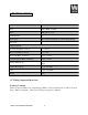
SPECIFICATIONS Item: 70712 Motor: 120V, 60Hz, 15 Amps Speed: 4300 rpm (no load) Blade Diameter: 12" Blade Type: 60-Tooth General Purpose Carbide Tipped Blade Arbor Size: 1" Cutting Capacity: Crosscut at 0ºMiter, 0ºBevel: 4" x 12-1/4" Miter at 45ºMiter, 0ºBevel: 4" x 8-1/4" Bevel at 0ºMiter, 45ºBevel: 2-1/8" x 12-1/4" Compound at 45ºMiter, 45ºBevel: 2-1/8" x 8-1/4" Positive Table Stops: 0º, 5º, 10º, 15º, 20º, 25º, 30º, 35º, 40ºand 45ºLeft & Right Positive Bevel Stops: 0º–45ºLeft Only
IMPORTANT SAFETY INSTRUCTIONS 1. The purpose of safety symbols is to attract your attention to possible dangers. The safety symbols, and the explanations with them, deserve your careful attention and understanding. The safety warnings do not by themselves eliminate any danger. The instructions or warnings they give are not substitutes for proper accident prevention measures. WARNING: This is a safety alert symbol. It is used to alert you to potential bodily injury hazards.
Work Area Safety 1. Keep your work area clean and well lit. Cluttered or dark areas invite accidents. 2. Do not operate your tool/equipment in explosive atmospheres, such as in the presence of flammable liquids, gases or dust. The motors produce sparks which may ignite the dust or fumes. 3. Keep children and bystanders a safe distance from the work area. 4. Make the work area childproof with padlocks, master switches and or by removing the starter keys. Electrical Safety 1.
WARNING: Some dust created by power sanding, sawing, grinding, drilling, and other construction activities contains chemicals known to cause cancer, birth defects or other reproductive harm. Some examples of these chemicals are: a) Lead from lead-based paints, b) crystalline silica from bricks and cement and other masonry products, c) Arsenic and chromium from chemically treated lumber. Your risk from these exposures varies, depending on how often you do this type of work.
6. Allow the motor to come up to full speed before starting a cut to avoid binding or stalling. 7. Never leave your Miter Saw unattended. Release the ON/OFF trigger and don't leave until the blade has come to a complete stop. 8. Disconnect the plug from the power source before making any adjustments, changing accessories, or storing your Miter Saw. This preventive safety measure reduces the risk of starting your Miter Saw accidentally. 9. Use the recommended accessories listed in this Operator's Manual.
WARNING: Do not operate your saw until it is assembled, and you have read and understood the following instructions as well as the warning labels on the saw. Miter Saw Preparation 1. Check for proper assembly and alignment of moving parts. (See Assembly Instructions, page 14.) 2. Read, understand, and follow all operating instructions and safety warnings in this Operator's Manual. 3. Know the condition of your Miter Saw.
ELECTRICAL INSTRUCTIONS Grounding Instructions 1. IN THE EVENT OF A MALFUNCTION OR BREAKDOWN, grounding provides the path of least resistance for electric current and reduces the risk of electric shock. This tool/equipment is equipped with an electric cord that has an equipment grounding conductor and a grounding plug. The plug MUST be plugged into a matching outlet that is properly installed and grounded in accordance with ALL local codes and ordinances. 2. DO NOT MODIFY THE PLUG PROVIDED.
Fig. 1 1. Tools/equipment with three wire grounding plugs (Fig. 1, A) are intended for use on a circuit that has an outlet that looks like the one illustrated (Fig. 1, B). 2. A temporary adapter (Fig. 1, D) may be used to connect this plug to a 2-pole receptacle (Fig. 1, C) if a properly grounded outlet is not available. 3. The temporary adapter should be used only until a properly grounded outlet can be installed by a qualified electrician. 4. The green colored rigid ear, lug, etc.
1. Be sure your extension cord is properly wired and in good condition. Always replace a damaged extension cord or have it repaired by a qualified person before using it. 2. Protect your extension cords from sharp objects, excessive heat and damp or wet areas. 3. Use a separate electrical circuit for your tools. This circuit must not be less than a #12 wire and should be protected with a 20 Amp time delayed fuse. 4.
COMPONENTS ASSEMBLY INSTRUCTIONS Extension Supports Attachment Insert the ends of the Extension Supports into the holes in the sides of the base. Tighten the Screws to hold the Extensions in place. The upper edge of the Extensions will be level with the surface of the saw. This provides a wider base for the work piece to rest on. Attach the Dust Collection Bag The Dust Collection Bag slips over the Dust Outlet behind the Blade Housing Assembly. Sawdust created by cutting is captured in the bag.
Note: the saw is shipped with the motor locked in the down position. To release the saw for use, push the handle downward with your left hand as if you were cutting a piece of wood. While holding the handle down, reach back to the handle latch (release knob) with your right hand and pull it out. Saw Mounting The Miter Saw must be mounted on a support before use. This may be a commercially available support or homemade saw table. There are bolt holes provided in each of the four legs of the base.
lock the Table into several often used miter angles. These angles are 0º(centered), 5º, 10º, 15º, 20º, 25º, 30º, 35º, 40ºand 45ºleft and right. 9. To make a bevel cut, release the Bevel Lock Lever, rotate the Blade Assembly to the desired bevel angle, then lock the Blade Assembly in place using the Bevel Lock Lever. For making bevel cuts see page 16. 10. This saw is provided with a Kerf Board. The Kerf Board helps to prevent tear-out on the bottom side of the work piece.
Bevel Angle Adjustment 1. A bevel cut is one that is at an angle to the vertical plane of the material. 2. Bevel cuts can be used to miter relatively wide and thin material. Bevel cuts can be used in combination with a miter cut to form a compound angle. Compound angle cuts are often used in crown moldings, picture frames and similar trim materials. 3. To set the bevel angle, loosen the Bevel Lock Handle at the rear of the saw.
Squaring the Saw Blade to the Guide Fence WARNING: Be sure that the Miter Saw is switched OFF and unplugged from the power source before performing any work on the tool. Failure to unplug the saw may result in accidental startup, causing possible serious bodily injury. 1. Unplug the Miter Saw. 2. Loosen the Miter Lock Knob. Rotate the Miter Table and move pointer to the 0ºposition. 3. Tighten the Miter Lock Knob securely. 4.
5. Slowly rotate the blade by hand, checking the square's alignment with the blade at several points. The edge of the square and blade should be parallel; however, if the top or bottom of the blade angles away from the square's edge, an adjustment is needed. 6. Using a wrench, loosen the Lock Nut (securing the positive bevel stop adjustment bolt in place). The 0ºbevel adjustment bolt (Fig. 5) is located on the rear right side of the Miter Table. 7.
9. When the cut is completed, raise the Blade Assembly, wait for the blade to stop turning, release the Hold Down Clamp and remove the work piece from the saw. Avoid Injury from Jams, Sips or Thrown Pieces 1. Use the correct 12" blade for the material and type of cut. Do not cut materials that may shatter, grab the blade or cause other danger. 2. Only use a blade that is sharp and in good condition. Check alignment of the blade after it is installed.
Cutting Odd Shapes, Oversize or Small Pieces 1. Plan your work so an odd shaped work piece cannot slip or pinch the blade. When cutting material like molding, it must lie flat or be held by a fixture. Do not allow the material to rock, twist or slip. 2. Secure sagging work pieces with sawhorses, tables or other additional supports. 3. Do not cut small work pieces that you must hold closer than 4 inches from the blade. 4. Properly support round material when cutting.
18. Test the operation of your saw prior to cutting a work piece. If you feel excessive vibration or hear an unusual noise, immediately stop operating the saw. Correct the problem before continued use. 19. Allow movement of the waste portion of the work piece. Do not hold it, clamp it, touch it or use a length stop against it. The cut-off waste portion must be free to move. It could become wedged against the blade causing a hazard. 20. Avoid awkward hand positions.
Blade Replacement 1. Unplug the tool from its power source. 2. Lock the Blade Assembly in the raised position by twisting in the Locking Pin. 3. Use the supplied wrench to remove the Center Cover Fixing Bolt holding the Center Cover in place by turning it counterclockwise (Fig. 6). 4. Raise the Blade Guard and Center Cover (Fig. 7). 5. While holding in the arbor lock button (see page 13), use the wrenches to loosen the Arbor Bolt by turning it clockwise. (Fig. 8) Fig.
5. If either test reveals that the cut is not a true 90ºangle, you must adjust the Guide Fence before beginning work. 6. To adjust the Guide Fence, first unplug the tool. 7. Lower the Blade Assembly and lock it in place using the Locking Pin. 8. Lay a reliable carpenter’s square on the Table with one edge along the blade and the other along the Guide Fence. Any inaccuracy should be visible. NOTE: The square must contact the surface of the blade, not the teeth, for an accurate reading. 9.
Miter Saw Cleaning and Lubricating 1. Observe the Dust Bag while using the saw. Empty the sawdust into an appropriate container when the bag is full. 2. Occasionally wipe or blow off sawdust that accumulates on the saw. Saw dust on the Guide Fence can cause you to make inaccurate cuts. 3. Keep the Slides free of sawdust. Wipe or blow them off as required. Use a dry lubricant on the slides. Do not use oil or grease lubricant, as this will attract dust. 4.
TROUBLESHOOTING Problem Miter Saw will not start. Likely Solutions Check power at outlet. Check that cord is plugged into outlet. Miter Saw operates Low power supply or Check power supply and sporadically or at low power. improper extension cords. power cords. Worn or cracked carbon Check Carbon Brushes. brushes. Replace if damaged or worn. Wood burns at ends when cut. Dirty blade. Clean blade using blade cleaner or mineral spirits. Material is binding. Check position of work piece on Table.
EXPLODED VIEW ITEM 70712 OPERATOR’S MANUAL 26
PARTS LIST Part # 1 2 3 4 5 6 7 8 9 10 11 12 13 14 15 16 17 18 19 20 21 22 23 24 25 26 27 28 29 30 31 32 33 34 35 36 37 38 39 40 41 42 43 Stock # 70712-001 70712-002 70712-003 70712-004 70712-005 70712-006 70712-007 70712-008 70712-009 70712-010 70712-011 70712-012 70712-013 70712-014 70712-015 70712-016 70712-017 70712-018 70712-019 70712-020 70712-021 70712-022 70712-023 70712-024 70712-025 70712-026 70712-027 70712-028 70712-029 70712-030 70712-031 70712-032 70712-033 70712-034 70712-035 70712-036 70712
Part # 87 88 89 90 91 92 93 94 95 96 97 98 99 100 101 102 103 104 105 106 107 108 109 110 111 112 113 114 115 116 117 118 119 120 121 Stock # 70712-087 70712-088 70712-089 70712-090 70712-091 70712-092 70712-093 70712-094 70712-095 70712-096 70712-097 70712-098 70712-099 70712-100 70712-101 70712-102 70712-103 70712-104 70712-105 70712-106 70712-107 70712-108 70712-109 70712-110 70712-111 70712-112 70712-113 70712-114 70712-115 70712-116 70712-117 70712-118 70712-119 70712-120 70712-121 Description PLASTI
ONE (1) YEAR LIMITED WARRANTY ® WEN is committed to building tools that are dependable for years. Our warranties are consistent with our commitment and dedication to quality. ONE (1) YEAR LIMITED WARRANTY OF WEN PRODUCTS FOR HOME USE. GREAT LAKES TECHNOLOGIES, LLC (“Seller") warrants to the original purchaser only, that all WEN consumer power tools will be free from defects in material or workmanship for a period of one (1) year from date of purchase.