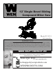
2˝ Single Bevel Sliding Compound Miter Saw Model # 70712 bit.ly/wenvideo IMPORTANT: Your new tool has been engineered and manufactured to WEN’s highest standards for dependability, ease of operation, and operator safety. When properly cared for, this product will supply you years of rugged, trouble-free performance. Pay close attention to the rules for safe operation, warnings, and cautions. If you use your tool properly and for intended purpose, you will enjoy years of safe, reliable service.
TABLE OF CONTENTS 2 3 4 5 7 8 12 15 16 19 Technical Data General Safety Rules Specific Safety Rules For Miter Saws Electrical Information Know Your Miter Saw Assembly and Adjustments Operation Maintenance Exploded View & Parts List Warranty TECHNICAL DATA Model Number: Motor: No Load Speed: Blade Size: Arbor Size: Number of Teeth: Miter Table Angles: Bevel Cuts: Weight: Cutting Capacity 0° Miter, 0° Bevel: 45° Miter, 0° Bevel: 0° Miter, 45° Bevel: 45° Miter, 45° Bevel: Includes: 2 70712 120 V, 60 Hz, 15
GENERAL SAFETY RULES Safety is a combination of common sense, staying alert and knowing how your item works. SAVE THESE SAFETY INSTRUCTIONS. WARNING: To avoid mistakes and serious injury, do not plug in your tool until the following steps have been read and understood. 1. READ and become familiar with this entire instruction manual. LEARN the tool’s applications, limitations, and possible hazards. 2. AVOID DANGEROUS CONDITIONS. Do not use power tools in wet or damp areas or expose them to rain.
GENERAL SAFETY RULES 14. NEVER STAND ON A TOOL. Serious injury could result if the tool tips or is accidentally hit. DO NOT store anything above or near the tool. 15. DO NOT OVERREACH. Keep proper footing and balance at all times. Wear oil-resistant rubber-soled footwear. Keep the floor clear of oil, scrap, and other debris. 16. MAINTAIN TOOLS PROPERLY. ALWAYS keep tools clean and in good working order. Follow instructions for lubricating and changing accessories. 17. CHECK FOR DAMAGED PARTS.
SPECIFIC RULES FOR MITER SAWS 13. Before making compound miter cuts, ensure that the work head is securely fixed in the desired position. 14. Rags, cloths, cord, string and the like should never be left around the work area. 15. Avoid cutting nails. Inspect workpieces and remove all nails and other foreign objects before beginning to saw. 16. Support the work properly. 17. Never reach over the blade to remove waste or cut-offs. 18. Do not attempt to free a jammed blade while the machine is still running.
ELECTRICAL INFORMATION GUIDELINES FOR USING EXTENSION CORDS Make sure your extension cord is in good condition. When using an extension cord, be sure to use one heavy enough to carry the current your product will draw. An undersized cord will cause a drop in line voltage resulting in loss of power and overheating. The table below shows the correct size to be used according to cord length and nameplate ampere rating. When in doubt, use a heavier cord. The smaller the gauge number, the heavier the cord.
KNOW YOUR MITER SAW A M B L K C D J I E F G H A B C D E F G Operating Handle ON/OFF Switch Lower Blade Guard Fence Miter Table Table Insert Miter Table Lock H I J K L M Miter Scale Bevel Lock Knob Slide Bar Slide Lock Knob Dust Extraction Port Guard Retraction Arm UNPACKING If you find any pieces that are missing or wrong, do not operate the tool until the parts have been replaced. Failure to do so could result in serious personal injury. 1. Remove all loose parts from the carton. 2.
ASSEMBLY AND ADJUSTMENTS TRANSPORTATION Only lift the miter saw after switching off the saw, locking down the saw arm, and unplugging the machine from its power source. Only lift the saw by the carrying handle located on top of the motor or by the outer castings. Do not lift the saw using the guard or the operating handle. BENCH MOUNTING The saw base has holes in each corner to facilitate bench mounting (FIGURE 1). 1.
ASSEMBLY AND ADJUSTMENTS BEVEL LOCK The bevel lock is used to set the blade at the desired bevel angle (FIGURE 5). The miter saw bevels from 0° to 45° left only. WARNING: Be sure to tighten the bevel lock before making a cut. Failure to do so could result in the saw arm moving during the cut and cause serious personal injury. HOLD DOWN CLAMP ASSEMBLY FIGURE 5 The hold down clamp assembly can be mounted to the fence on either side of the saw blade depending on what suits the task at hand.
ASSEMBLY AND ADJUSTMENTS TURNING ON AND OFF 1. Pull the ON/OFF trigger switch found inside the front handle to start the miter saw. 2. To turn the saw off, release the ON/OFF trigger switch. SETTING THE TABLE SQUARE WITH THE BLADE 1. Make sure that the power cord is removed from the power source. 2. Push the saw arm down to its lowest position and engage the release knob (FIGURE 2). 3. Loosen the miter table lock (FIGURE 4). 4. Rotate the table until the pointer is positioned at 0°. 5.
ASSEMBLY AND ADJUSTMENTS SETTING THE FENCE SQUARE WITH THE TABLE 1. Make sure that the power cord is removed from the power source. 2. Push the saw arm down to it lowest position and engage the release knob (Figure 2) to hold the saw arm in the transport position. 3. Loosen the miter table lock (FIGURE 4). 4. Rotate the table until the pointer is positioned at 0°. 5. Tighten the miter lock (FIGURE 4). 6. Using the hex key, loosen the four screws securing the fence to the base (FIGURE 15). 7.
CAUTION: To ensure the correct blade rotation, always install the blade with the blade teeth and the arrow printed on the side of the blade pointing downwards. The direction of the blade’s rotation is also stamped with an arrow on the upper blade guard. 12. Replace the outer flange. 13. Depress the spindle lock button (Figure 7) and replace the arbor bolt. 14. Use the hex key to tighten the arbor bolt securely (tighten in a counterclockwise direction). 15.
OPERATION CROSS-CUTTING WITH SLIDE ACTION When cutting wide work pieces, first unscrew the slide lock knob. 1. Pull on the release knob (FIGURE 2), raise the saw arm to its highest position and slide it towards you (FIGURE 22). 2. Hold the handle firmly and squeeze the switch trigger. Allow the blade to reach maximum speed. 3. Slowly lower the blade into the workpiece while pushing it away from you until the workpiece is cut. 4.
OPERATION COMPOUND MITER CUT A compound miter cut involves using a miter angle and a bevel angle at the same time (FIGURE 24). Always make a test cut on a piece of scrap wood before cutting into good material. Use the slide action when cutting wide workpieces. 1. Pull on the release knob (FIGURE 2) and lift the saw arm to its full height. 2. Loosen the miter lock (FIGURE 4). 3. Rotate the miter table until the pointer aligns with the desired angle on the miter scale. 4. Retighten the miter lock (FIGURE 4).
MAINTENANCE WARNING: Always ensure that the tool is switched off and the plug is removed from the outlet before making any adjustments or maintenance procedures. •Any damage to this tool should be repaired and carefully inspected by qualified repair personnel before use. •Have your power tool serviced by a qualified repair person using only identical replacement parts. This will maintain the safety of the power tool.
EXPLODED VIEW & PARTS LIST 16
EXPLODED VIEW & PARTS LIST Item 1 2 3 4 5 6 7 8 9 10 11 12 13 14 15 16 17 18 19 20 21 22 23 24 25 26 27 28 29 30 31 32 33 34 35 36 37 38 39 40 41 42 43 44 45 46 47 48 49 50 51 52 Stock # 70712B-001 70712B-002 70712B-003 70712B-004 70712B-005 70712B-006 70712B-007 70712B-008 70712B-009 70712B-010 70712B-011 70712B-012 70712B-013 70712B-014 70712B-015 70712B-016 70712B-017 70712B-018 70712B-019 70712B-020 70712B-021 70712B-022 70712B-023 70712B-024 70712B-025 70712B-026 70712B-027 70712B-028 70712B-029 70712
EXPLODED VIEW & PARTS LIST Item 105 106 107 108 109 110 111 112 113 114 115 116 117 118 119 120 121 122 123 124 125 18 Stock # 70712B-105 70712B-106 70712B-107 70712B-108 70712B-109 70712B-110 70712B-111 70712B-112 70712B-113 70712B-114 70712B-115 70712B-116 70712B-117 70712B-118 70712B-119 70712B-120 70712B-121 70712B-122 70712B-123 70712B-124 70712B-125 Description Bolt Up handle switch button Spring Switch Down handle Press line plank Bolt Cable shell Power cord Bolt Nut Small cover slice Big cover
LIMITED ONE YEAR WARRANTY WEN Products is committed to build tools that are dependable for years. Our warranties are consistent with this commitment and our dedication to quality. LIMITED WARRANTY OF WEN CONSUMER POWER TOOLS PRODUCTS FOR HOME USE GREAT LAKES TECHNOLOGIES, LLC (“Seller”) warrants to the original purchaser only, that all WEN consumer power tools will be free from defects in material or workmanship for a period of one (1) year from date of purchase.
Thanks for remembering 20