TABLE OF CONTENTS Specifications ……………………………………………………………………………………… General safety rules………………………………………………………………………………... Additional safety rules for miter saws ……………………………………………………………... Know your product ………………………………………………………………………………… Operation and adjustments …………………………………………………………………………. Unpacking ………………………………………………………………………………… Transportation …………………………………………………………………………….. Bench mounting …………………………………………………………………………...
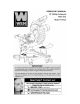
Specifications Model Number Input Power No Load Speed Blade Size Number of teeth MiterTable Angles Bevel Cuts Weight 70716 120V, 60Hz, 15A 5500 RPM 10" x 5/8" bore 60 0° to 52° Left & Right 0° to 45° Left only 29.
General safety rules WARNING:Read all safety warnings and instructions. Failure to follow the warnings and instructions may result in electric shock, fire and/or serious injury. Save all warnings and instructions for future reference. The term “power tool” in the warnings refers to your operated (corded) power tool. 1. Work area safety a. b. c. 2. Electrical safety a. b. c. d. e. f. 3. Keep work area clean and well lit. Cluttered or dark areas invite accidents.
4. Power tool use and care a. b. c. d. e. f. g. h. i. 5. Do not force the power tool. Use the correct power tool for your application. The correct power tool will do the job better and safer at the rate for which it was designed. Do not use the power tool if the switch does not turn it on and off. Any power tool that cannot be controlled with the switch is dangerous and must be repaired.
Additional safety rules for miter saws • • • • • • • • • • • • • • • • • • • • • • • • • • • Ensure that the lighting is adequate. Do not use the saw unless the guards are in place. Do not use the saw to cut metal or masonry. Keep the area free of tripping hazards. Do not let anyone under 18 years operate this saw. Always stand to one side when operating the saw. Never use damaged or deformed saw blades. Only use sharp blades.
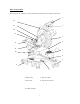
Know your product Before using the saw, familiarize yourself with all the operating features and safety requirements. 1 16 15 2 14 13 3 4 12 11 5 10 6 7 9 8 1. Operating Handle 2. ON/OFF Switch 3. Blade Guard 4. Fence 5. Miter Table 6. Table Insert 7. Miter Lock 8. Miter Scale 9. Support Arm 10. Clamp Assembly 11. Bevel Lock Knob 12. Slide Bar 13. Slide Lock knob 14. Dust Extraction Port 15. Guard Retraction Arm 16.
Operation and adjustments Unpacking Due to modern mass production techniques, it is unlikely that your WEN® tool is faulty or that a part is missing. However,if you find anything wrong, do not operate the tool until the parts have been replaced or the fault has been rectified. Failure to do so could result in serious personal injury. 1. Remove all loose parts from the carton. 2. Remove the packing materials from around the saw. 3.
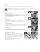
Bevel lock The bevel lock (11) is used to set the blade at the desired bevel angle (Fig. 5). The miter saw bevels from 0° to 45° left. WARNING: Be sure to tighten the bevel lock before making a cut. Failure to do so could result in the saw arm moving during the cut and cause serious personal injury. Fig. 6 Hold down clamp assembly The hold down clamp assembly can be mounted to the fence on either side of the saw bladedepending onwhat suits the task at hand.
Trench depth adjustment In its normal position, the trenching stop permits the saw blade to cut right through a workpiece. When the saw arm is lifted, the trenching stop can be moved to the left so that the trenching depth adjustment screw contacts the stop as the saw arm is lowered. (Fig.11).This restricts the cut to a specific “trench” in the workpiece. The depth of the trench can be adjusted with the trenching depth adjustment screw (Fig. 12) and locked in position with the trenching depth lock nut(Fig.
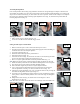
Setting the fence square with the table 1. 2. Make sure that the power cord is removed from the power source. Push the saw arm down to its lowest position and engage the release knob (Fig. 24) to hold the saw arm in the transport position. 3. Loosen the miter lock (Fig. 15). 4. Rotate the table until the pointer is positioned at 0º. 5. Tighten the miter lock (Fig. 15). 6. Using the 6mm hex key provided, loosen the four screws securing the fence to the base (Fig. 21). 7.
CAUTION:To ensure correctblade rotation, always installthe blade with the bladeteeth and the arrow printedon the side of the bladepointing downwards. The direction of the blade’s rotation is alsostamped with an arrow on the upper blade guard. 12. Replace the outer flange (Fig. 31). 13. Depress the spindle lock button (Fig. 28) and replace the flat washer and arbor bolt. 14. Use the 6mm hex key to tighten the arbor bolt securely (tighten in a counterclockwise direction). 15.
10. Hold the operating handle (1) firmly and squeeze the switch trigger. Allow the blade to reach maximum speed and slowly lower the blade into and through the workpiece. 11. Release the switch trigger and allow the saw blade to stop rotating before raising the blade out of the workpiece. Wait until the blade stops before removing the workpiece. Cross-cutting (with slide action) Fig. 35 When cutting wideworkpieces, first unscrew theslide lock knob(13). 1. Pull on the release knob (Fig.
4. Retighten the miter lock (Fig. 15). WARNING: Be sure to tighten the miter lock before makinga cut. Failure to do so could result in the table movingduring the cut, causing serious personal injury. 5. Loosen the bevel lock (Fig. 16) and pull out the 0º bevel adjuster and move the saw arm to the left or right to the desired bevel angle (between 0º and 45º). Tighten the bevel lock (Fig. 16). 6. Place the workpiece flat on the table with one edge securely against the fence.
Maintenance WARNING: Always ensure that the tool is switched off and the plug is removed from the outlet before making any adjustments or maintenance procedures. • Any damage to this tool should be repaired and carefully inspected by qualified repair personnel before use. • Have your power tool serviced by a qualified repairperson using only identical replacement parts. This will ensure that the safety of the power tool is maintained.
Exploded view and parts list 16
Item 1 2 3 4 5 6 7 8 9 10 11 12 13 14 15 16 17 18 19 20 21 22 23 24 25 26 27 28 29 32 33 34 35 36 37 38 Stock # 70716-001 70716-002 70716-003 70716-004 70716-005 70716-006 70716-007 70716-008 70716-009 70716-010 70716-011 70716-012 70716-013 70716-014 70716-015 70716-016 70716-017 70716-018 70716-019 70716-020 70716-021 70716-022 70716-023 70716-024 70716-025 70716-026 70716-027 70716-028 70716-029 70716-032 70716-033 70716-034 70716-035 70716-036 70716-037 70716-038 Description Screw Motor cover Screw Br
Item 88 89 90 97 98 99 100 101 102 103 104 105 106 107 108 109 110 111 112 113 114 115 116 117 118 119 120 121 122 123 124 125 126 127 128 129 130 131 132 Stock # 70716-088 70716-089 70716-090 70716-097 70716-098 70716-099 70716-100 70716-101 70716-102 70716-103 70716-104 70716-105 70716-106 70716-107 70716-108 70716-109 70716-110 70716-111 70716-112 70716-113 70716-114 70716-115 70716-116 70716-117 70716-118 70716-119 70716-120 70716-121 70716-122 70716-123 70716-124 70716-125 70716-126 70716-127 70716-12
Limited two years warranty WEN® Products is committed to build tools that are dependable for years. Our warranties are consistent with this commitment and our dedication to quality LIMITED WARRANTY OF WEN® CONSUMER POWER TOOLS PRODUCTS FOR HOME USE GREAT LAKES TECHNOLOGIES, LLC ("Seller") warrants to the original purchaser only, that all WEN® consumer power tools will be free from defects in material or workmanship for a period of two (2) years from date of purchase.