OPERATOR’S MANUAL 10" Dual Bevel Sliding Compound Miter Saw Model # 70751 IMPORTANT Your new tool has been engineered and manufactured to Apex Pro’s high standards for dependability, ease of operation, and operator safety. Properly cared for, it will give you years of rugged, trouble-free performance. Pay close attention to the Rules for Safe Operation, Warnings, and Cautions. If you use your tool properly and only for what it is intended, you will enjoy years of safe, reliable service.
TABLE OF CONTENTS Specifications ……………………………………………………………………………………… General safety rules ………………………………………………………………………………... Safety rules for laser lights ………………………………………………………………………… Additional safety rules for miter saws ……………………………………………………………... Know your product ………………………………………………………………………………… Operation and adjustments …………………………………………………………………………. Unpacking ………………………………………………………………………………… Transportation …………………………………………………………………………….. Bench mounting …………………………………………………………………………...
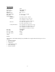
Specifications Model Number Input Power No Load Speed Blade Size Number of teeth Miter Table Angles Bevel Cuts Cutting Capacity Straight cut Miter cut Bevel cut Compound miter cut Laser type Laser class Laser wave length Laser Max.
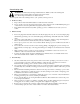
General safety rules WARNING: Read all safety warnings and all instructions. Failure to follow the warnings and instructions may result in electric shock, fire and/or serious injury. Save all warnings and instructions for future reference. The term “power tool” in the warnings refers to your operated (corded) power tool. 1. Work area safety a. b. c. 2. Electrical safety a. b. c. d. e. f. 3. Keep work area clean and well lit. Cluttered or dark areas invite accidents.
4. Power tool use and care a. b. c. d. e. f. g. h. i. 5. Do not force the power tool. Use the correct power tool for your application. The correct power tool will do the job better and safer at the rate for which it was designed. Do not use the power tool if the switch does not turn it on and off. Any power tool that cannot be controlled with the switch is dangerous and must be repaired.
Additional safety rules for miter saws Ensure that the lighting is adequate. Do not use the saw unless the guards are in place. Do not use the saw to cut metal or masonry. Keep the area free of tripping hazards. Do not let anyone under 18 years operate this saw. Always stand to one side when operating the saw. Never use damaged or deformed saw blades. Only use sharp blades.
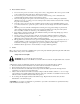
Know your product Before using the saw, familiarize yourself with all the operating features and safety requirements. 1. Operating handle 2. Release latch 3. 1/4” (6mm) Hex key 4. Blade bolt cover 5. Rotating blade guard 6. Laser light assembly 7. Bevel scale 8. Fence 9. Miter table 10. Miter table lock 11. Miter release lever 12. Table insert (kerf plate) 13. Miter scale 14. Side support bars (x2) 15. Side support bar location holes (2 sets) 16. Clamp assembly lock (x2) 17. Bevel lock 18.
Operation and adjustments Unpacking Due to modern mass production techniques, it is unlikely that your Apex Pro™ Power Tool is faulty or that a part is missing. However, if you find anything wrong, do not operate the tool until the parts have been replaced or the fault has been rectified. Failure to do so could result in serious personal injury. 1. Remove all loose parts from the carton. 2. Remove the packing materials from around the saw. 3.
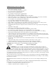
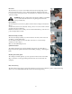
Bevel lock The bevel lock (17) is used to set the blade at the desired bevel angle (Fig. 5). The miter saw bevel cuts from 0°to 45°to the left and right. To adjust the bevel angle loosen the bevel lock and pull out the 0°bevel adjuster (31). Adjust the saw arm to the desired bevel angle. WARNING: Be sure to tighten the bevel lock before making a cut. Failure to do so could result in the saw arm moving during the cut and cause serious personal injury.
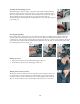
Attaching the material support arms The material support arms (14) help to support the material when working with long workpieces. There are two location holes (15) for a support arm on either side of the table. Loosen the lock knobs on the back of the base at the bottom. Ensure the support arms are fully inserted before using them to support the workpiece (Fig. 10). The material support arm locking knobs must be tightened to secure the support arms in position (Fig. 11).
Setting the table square with the blade 1. 2. Make sure that the electrical plug is removed from the outlet. Push the saw arm (34) down to its lowest position and engage the release knob (6) to hold the saw arm in the transport position. 3. Loosen the miter lock (10) (Fig. 17). 4. Rotate the table (9) until the pointer is positioned at 0º. 5. Tighten the miter lock (10). 6. Loosen the bevel lock (17) and set the saw arm (5) at 0ºbevel (the blade at 90ºto the miter table). Tighten the bevel lock (17) (Fig.
Setting the fence square with the table 1. 2. 3. 4. 5. 6. 7. 8. 9. 10. 11. 12. 13. Make sure that the electrical plug is removed from the outlet. Push the saw arm (34) down to its lowest position and engage the release knob (6) to hold the saw arm in the transport position. Loosen the miter lock (10). Rotate the table (9) until the pointer is positioned at 0º. Tighten the miter lock (10). Using the 6mm hex key loosen the hex screw securing the top piece of the right hand side fence (Fig.
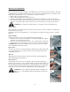
7. Hold the rotating guard (5) up and press the spindle lock button (25) (Fig. 33). Rotate the blade until the spindle locks. 8. Use the 6mm hex key provided to loosen and remove the blade bolt. (Loosen in a clockwise direction as the blade screw has a left hand thread) (Fig. 34). 9. Remove the flat washer and outer blade washer and the blade. 10. Wipe a drop of oil onto the inner blade washer and the outer blade washer where they contact the blade. 11.
10. Hold the operating handle (1) firmly, depress lock off button (25) and squeeze the switch trigger (28) (Fig. 41). Allow the blade to reach maximum speed and slowly lower the blade into and through the workpiece. 11. Release the switch trigger (28) and allow the saw blade to stop rotating before raising the blade out of the workpiece. Wait until the blade stops before removing the workpiece. Cross-cutting (with slide action) When cutting wide workpieces, first unscrew the slide lock (20). 1.
3. Rotate the miter table (9) until the pointer aligns with the desired angle on the miter scale (13). 4. Retighten the miter lock (10). WARNING: Be sure to tighten the miter lock before making a cut. Failure to do so could result in the table moving during the cut, causing serious personal injury. 5. Loosen the bevel lock (17) and pull out the 0ºbevel adjuster (31) and move the saw arm (34) to the left or right to the desired bevel angle (between 0ºand 45º). Tighten the bevel lock (17). 6.
Maintenance WARNING: Always ensure that the tool is switched off and the plug is removed from the outlet before making any adjustments or maintenance procedures. Any damage to this tool should be repaired and carefully inspected before use, by qualified repair personnel. Have your power tool serviced by a qualified repair person using only identical replacement parts. This will ensure that the safety of the power tool is maintained.
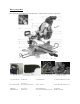
Exploded view and parts list 17
Part # 1 2 4 5 6 7 8 9 10 11 12 13 14 15 16 17 18 19 20 21 22 23 24 25 26 27 28 29 30 31 32 33 34 35 36 37 38 39 40 41 42 43 44 45 46 Stock # 70751-001 70751-002 70751-004 70751-005 70751-006 70751-007 70751-008 70751-009 70751-010 70751-011 70751-012 70751-013 70751-014 70751-015 70751-016 70751-017 70751-018 70751-019 70751-020 70751-021 70751-022 70751-023 70751-024 70751-025 70751-026 70751-027 70751-028 70751-029 70751-030 70751-031 70751-032 70751-033 70751-034 70751-035 70751-036 70751-037 70751-038
Part # 95 96 97 98 99 100 101 102 103 104 105 106 107 108 109 110 111 112 113 114 115 116 117 118 119 120 121 122 123 124 125 126 127 128 129 130 131 132 133 134 135 136 137 138 139 Stock # 70751-095 70751-096 70751-097 70751-098 70751-099 70751-100 70751-101 70751-102 70751-103 70751-104 70751-105 70751-106 70751-107 70751-108 70751-109 70751-110 70751-111 70751-112 70751-113 70751-114 70751-115 70751-116 70751-117 70751-118 70751-119 70751-120 70751-121 70751-122 70751-123 70751-124 70751-125 70751-126 7
Part # 185 186 187 188 189 190 191 192 193 194 195 196 200 201 202 203 204 205 206 207 208 209 210 211 213 214 215 221 222 223 Stock # 70751-185 70751-186 70751-187 70751-188 70751-189 70751-190 70751-191 70751-192 70751-193 70751-194 70751-195 70751-196 70751-200 70751-201 70751-202 70751-203 70751-204 70751-205 70751-206 70751-207 70751-208 70751-209 70751-210 70751-211 70751-213 70751-214 70751-215 70751-221 70751-222 70751-223 Description Turntable bolt cover Spring washer Screw Miter pointer Spring w
Limited two years warranty APEX PRO Products is committed to build tools that are dependable for years. Our warranties are consistent with this commitment and our dedication to quality LIMITED WARRANTY OF APEX PRO CONSUMER POWER TOOLS PRODUCTS FOR HOME USE GREAT LAKES TECHNOLOGIES, LLC ("Seller") warrants to the original purchaser only, that all APEX PRO consumer power tools will be free from defects in material or workmanship for a period of two (2) years from date of purchase.