MODEL DF250iX 2500W DUAL FUEL INVERTER GENERATOR Instruction Manual NEED HELP? CONTACT US! Have product questions? Need technical support? Please feel free to contact us: 1-800-232-1195 (M-F 8AM-5PM CST) TECHSUPPORT@WENPRODUCTS.COM IMPORTANT: Your new tool has been engineered and manufactured to WEN’s highest standards for dependability, ease of operation, and operator safety. When properly cared for, this product will supply you years of rugged, trouble-free performance.
CONTENTS WELCOME 3 Specifications.................................................................................................... 3 Introduction...................................................................................................... 4 SAFETY 5 Safety Information............................................................................................ 5 Generator Safety Warnings...............................................................................
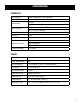
SPECIFICATIONS GENERATOR Rated Wattage Gasoline: 2000 Watts; LPG: 1800 Watts Surge Wattage Gasoline: 2500 Watts; LPG: 2250 Watts Rated Voltage Rated Amperage AC: 120V DC: 5V AC: 16.6A (Gasoline), 15A (LPG) DC: 1A (Top), 2.1A (Bottom) Phase Single Frequency 60 Hz Decibel Rating 52 dBA (No Load) Length: 19 Inches Product Dimensions Width: 11.5 Inches Height: 18.2 Inches Product Net Weight 48.
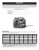
INTRODUCTION Thanks for purchasing the WEN 2500-Watt Dual-Fuel Inverter Generator. Refer to the illustration below for the location of the serial number on the side of the engine. Record the generator information in the spaces provided below. If assistance for information or service is required, please contact customer service by calling 1-800-232-1195, M-F 8-5 CST; you will be asked to provide the following generator information when calling.
SAFETY INFORMATION WARNING! Before operating the generator, make sure to read all safety warnings and all instructions. Failure to follow the warnings and instructions may result in electric shock, fire or serious injury. SAFETY INTRODUCTION Safety is a combination of common sense, staying alert, and knowing how your tool works. This manual contains important information regarding the generator’s potential safety concerns, as well as preparation, operation, and maintenance instructions.
GENERATOR SAFETY WARNINGS DANGER! CARBON MONOXIDE Using a generator indoors CAN KILL YOU IN MINUTES. Generator exhaust contains carbon monoxide (CO). This is a poison gas you cannot see or smell. If you can smell the generator exhaust, you are breathing CO. But even if you cannot smell the exhaust, you could be breathing CO. NEVER use a generator inside homes, garages, crawl spaces, or other partially enclosed areas. Deadly levels of carbon monoxide can build up in these areas.
GENERATOR SAFETY WARNINGS WARNING! Do not let comfort or familiarity with the product replace strict adherence to product safety rules. Failure to follow the safety instructions may result in serious personal injury. OPERATING ENVIRONMENT 1. Using a generator indoors can kill you in minutes. Only use a generator outside and far away from windows, doors and vents. 2. Do not smoke near the generator. 3. Do not operate near open flame, heat, or flammable materials.
GENERATOR SAFETY WARNINGS WARNING! Do not let comfort or familiarity with the product replace strict adherence to product safety rules. Failure to follow the safety instructions may result in serious personal injury. TO MAXIMIZE THE LIFESPAN OF YOUR GENERATOR: We recommend running your generator at least once a month for 20 to 30 minutes. Start the generator according to the instructions and plug a small load in to make sure the outlet is producing electricity.
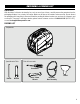
UNPACKING & PACKING LIST UNPACKING With the help of a friend or trustworthy foe, such as one of your in-laws, carefully remove the generator from the packaging and place it on a sturdy, flat surface. Make sure to take out all contents and accessories. Do not discard the packaging until everything is removed. Check the packing list below to make sure you have all of the parts and accessories.
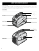
KNOW YOUR INVERTER GENERATOR TOOL PURPOSE Inverter Generators provide you with clean and quiet power, when and where you need it most. Refer to the following diagrams to become familiarized with all the parts and controls of your Generator. The components will be referred to later in the manual for assembly and operation instructions.
KNOW YOUR INVERTER GENERATOR CONTROL PANEL 1 2 3 4 11 10 9 8 7 6 5 1. 3-In-1 Dial Switch Off, Run, Half-Choke, Choke. 6. DC 5V USB Port 1A & 2.1A for charging various electronic devices. 2. Indication Lights Low Oil (Yellow), Overload (Red), & Output (Green). 7. Parallel Connection Connect to share wattage between inverter generators 3. CO WATCHDOG Carbon Monoxide Monitor Measures the accumulation of poisonous CO gas while the generator is running.
GENERATOR PREPARATION The following section describes the necessary steps to prepare the generator for use. If you are unsure about how to perform any of the steps please call 1-(800) 232-1195 M-F 8-5 CST for customer service. Failure to perform these steps properly can damage the generator or shorten its life. STEP 1 - ADD / CHECK OIL The generator is shipped without oil. User must add the proper amount of oil before operating the generator for the first time.
GENERATOR PREPARATION For subsequent operation, the oil level should be checked before each use, or after every 8 hours of operation. The generator is equipped with a low-oil sensor and will NOT start without a sufficient amount of oil. To check oil level (before every subsequent start): Fig. 4 1. Place the generator on a level surface. Make sure the engine is OFF before adding or checking oil. 2. Open the oil access cover. Remove and wipe the dipstick with a clean rag. 3.
GENERATOR PREPARATION STEP 2 - ADD / CHECK FUEL FUEL OPTION A: GASOLINE WARNING! RISK OF EXPLOSION. HIGHLY FLAMMABLE: This generator may emit highly flammable and explosive gasoline vapors, which can cause severe burns or even death, if ignited. A nearby open flame can lead to explosion even if not directly in contact with gasoline. • Do not operate near open flame, heat, or any other ignition source. Do not smoke near the generator. • Always operate on a firm, level surface.
GENERATOR PREPARATION STEP 2 - ADD / CHECK FUEL (CONTINUED) FUEL OPTION B: LIQUID PETROLEUM GAS (LPG) To connect your generator to an LPG cylinder: Fig. 7 1. Take off the safety caps from the cylinder valve, generator mounted regulator, and regulator connecting hose ends. 2. With the LPG tank valve closed, attach the LPG regulator connecting hose to the valve. Turn the plastic coupling from the hose right (clockwise) to tighten hose assembly onto the LPG tank (Fig. 7). 3.
GENERATOR PREPARATION AUTO FUEL SELECTION Your generator is equipped with Auto Fuel Selection Technology. What this means is that the generator will automatically select the fuel source (LPG or gasoline) depending on availability. LPG is prioritized; this means that if a propane tank with enough LPG is connected, the generator will automatically use LPG. If no propane tank is connected, or if there is no LPG remaining in the tank, the generator will use gasoline (if there is gasoline in the fuel tank).
GENERATOR PREPARATION STEP 3 - GROUND THE GENERATOR Fig. 10 To reduce the risk of electric shock and to maximize safety, the generator should be properly grounded. Ground the generator by tightening the grounding nut on the front control panel (Fig. 10) against a grounding wire. A generally acceptable grounding wire is a No. 12 AWG (American Wire Gauge) stranded copper wire. This grounding wire should be connected at the other end to a copper, brass, or steel-grounding rod that is driven into the earth.
STARTING YOUR GENERATOR Before starting the generator, make sure you have read and performed the steps in the “Generator Preparation” section of this manual. If you are unsure about how to perform any of the steps in this manual please call 1-(800) 232-1195 M-F 8-5 CST for customer service. DANGER! CARBON MONOXIDE Using a generator indoors CAN KILL YOU IN MINUTES. Generator exhaust contains carbon monoxide (CO). This is a poison gas you cannot see or smell.
STARTING YOUR GENERATOR Before starting the generator, check the following: 1. Place the generator outside on a dry, level surface. Allow at least two feet of clearance on all sides of the generator. Fig. 11 2. Make sure all electrical devices are unplugged from the generator during ignition. Otherwise it will be difficult for the engine to start. 3. To maximize safety, check that the generator is properly grounded (see “GROUND THE GENERATOR” section). 2 4.
STARTING YOUR GENERATOR When starting your generator in low temperatures (below 32º F): 1. Turn the 3-in-1 switch to the "Choke" position (Fig. A). Fig A 2. Use the recoil starter handle to start the generator (Fig. B). 3. Turn the 3-in-1 switch to the "Half Choke" position for about 15 seconds. This allows the generator to run stably, and the engine to warm up. NOTE: This is only required if you are operating in low temperatures below freezing (32º F). 4.
USING YOUR GENERATOR CALCULATING THE WATTAGE OF YOUR DEVICE(S) Connect electrical devices running on AC current according to their wattage requirements. Calculate the total running wattage and starting wattage of the device(s) you wish to connect, and MAKE SURE that they are within the capacity of your generator and the capacity of each individual outlet.
USING YOUR GENERATOR CALCULATING THE WATTAGE OF YOUR DEVICE(S) - CONTINUED The chart below serves as a reference for the estimated wattage requirements of common electrical devices. However, do not solely rely on this chart - all electronics and appliances are built differently. Always check the wattage listed on the electrical device before consulting this chart.
USING YOUR GENERATOR CONNECTING ELECTRICAL DEVICES When the rated wattage requirement of each electrical device has been determined, add these numbers to find the total rated wattage needed. If this number exceeds the rated wattage (2000W gasoline, 1800W LPG) of the generator, DO NOT connect all these devices. Select a combination of electrical devices with a total rated wattage lower than or equal to the rated wattage of the generator. CAUTION! Become familiar with the markings on the control panel (Fig.
USING YOUR GENERATOR ECO-MODE SWITCH This generator is equipped with an Eco-Mode Idle Control Switch. Engaging this switch allows the system to regulate the engine speed and automatically adjust its fuel consumption to match the required load. When the electrical load changes, the generator engine will automatically speed up and slow down as needed. This reduces fuel consumption and noise levels, while extending runtime and engine’s lifespan.
USING YOUR GENERATOR SOME NOTES ABOUT POWER CORDS Long or thin cords can drain the power provided to an electrical device by the generator. When using such cords, allow for a slightly higher rated wattage requirement by the electrical device. Device Requirements Amps 2.5 5 7.5 10 15 20 25 30 40 Watts (120V) 300 600 900 1200 1800 2400 3000 3600 4800 *NR = Not Recommended Max.
USING YOUR GENERATOR CO SENSOR INFORMATION The CO Watchdog carbon monoxide monitoring system (Fig. 14 - 1) measures the accumulation of poisonous CO gas while the generator is running. If the level of CO gas gets too high, the CO Watchdog system will automatically shut down the generator. This system is not a substitute for an indoor CO alarm. Whenever the CO Watchdog system shuts down the generator, the LED on the generator control panel (Fig.
SHUTTING OFF YOUR GENERATOR CAUTION! Unplugging running devices can cause damage to the generator. Never stop the engine with electrical devices connected and running. OPTION 1A: AUTOMATIC FUEL SHUTOFF (RECOMMENDED – GASOLINE ONLY) The WEN 2500W Inverter Generator is equipped with automatic fuel shutoff. This feature turns off the flow of fuel, allowing for the generator to use up the remaining fuel from the carburetor before turning off.
SHUTTING OFF THE GENERATOR CAUTION! Unplugging running devices can cause damage to the generator. Never stop the engine with electrical devices connected and running. OPTION 2: MANUAL SHUTOFF In case you are in a hurry and do not want to wait for the generator to automatically shut down, the manual shutoff feature is available. However, this method will leave stagnant fuel in the carburetor, possibly causing blockages, a shortened lifespan, and other maintenance issues.
MAINTENANCE Proper routine maintenance of the generator will help prolong the life of the machine. Please perform maintenance checks and operations according to the schedule in Table 4. CAUTION! Never perform maintenance operations while the generator is running. Before maintaining or servicing the generator, turn OFF the generator, disconnect all devices and allow the generator to cool down.
MAINTENANCE CLEANING THE GENERATOR Keep the generator clean to prevent improper operation or machine damage from dirt and debris. Inspect all ventilation openings on the generator. These openings must be kept clean and unobstructed. If the generator becomes dirty, use a damp cloth to wipe exterior surfaces. Use a soft bristle brush to loosen dirt and oil and use a vacuum to pick up loose dirt. Use low pressure air (not to exceed 25 PSI) to blow away dirt.
MAINTENANCE DRAINING THE CARBURETOR We recommended draining the carburetor after every use (not necessary if the generator is shut off using the “FUEL OFF” option), and before storing the generator. Draining the carburetor can prevent the fuel from clogging up the carburetor and preventing the generator from starting. 1. Place generator on elevated platform such as table or desk. Fig. 18 2.
MAINTENANCE AIR FILTER MAINTENANCE Check every 50 hours of operation (refer to Table 4 - Recommended Maintenance Schedule). Routine maintenance of the air filter helps maintain proper airflow to the carburetor. Occasionally check that the air cleaner is free of excessive dirt. To inspect and clean the air filter: 1. Using a Phillips-head screwdriver (not included), remove the service panel by unscrewing the three Phillips-head screws (Fig. 18) along the upper edge. Fig. 20 2.
MAINTENANCE DRAINING/CHANGING OIL Change the oil according to the Recommended Maintenance Schedule in Table 4. Change the oil MORE OFTEN if operating under heavy load or high ambient temperatures. It is also necessary to drain the oil from the crankcase if it has become contaminated with water or dirt. Changing the oil when the engine is warm allows for complete drainage. 1. Close the gas cap and vacuum relief valve. 2.
MAINTENANCE SPARK PLUG MAINTENANCE Refer to Recommended Maintenance Schedule in Table 4 for maintaining the spark plug. The spark plug is important for proper engine operation. Check the spark plug regularly to maintain proper engine operation. A good spark plug should be intact, free of deposits, and properly gapped. To inspect or replace the spark plug: 1. Using a Phillips-head screwdriver (not included), remove the service panel by unscrewing the three Phillips-head screws along the upper edge.
MAINTENANCE SPARK ARRESTOR MAINTENANCE Inspect and clean the spark arrestor every 100 hours of operation. The spark arrester is located outside the muffler, which gets very hot during operation. Allow the engine to cool completely before servicing the spark arrester. To inspect and clean the spark arrester: 1. Remove the screw that secures the spark arrestor to the muffler. Fig. 24 2. Remove the spark arrestor screen (Fig. 24). 3.
TRANSPORTATION & STORAGE TRANSPORTING THE GENERATOR To prevent fuel spillage when transporting, be sure to perform the following: 1. Tighten the fuel cap and turn the vacuum relief valve to “OFF”. 2. Set the engine switch to “OFF”. 3. Drain the fuel tank if possible (see “DRAINING THE FUEL TANK”). 4. Keep the generator upright. Never place the generator on its side or upside down - doing so will make it difficult to start. WARNING! Avoid direct sunlight inside a vehicle.
TROUBLESHOOTING GUIDE WARNING! Stop using the generator immediately if any of the following problems occur or risk serious personal injury. If you have any questions, please contact our customer service at 1-(800) 232-1195, M-F 8-5 CST or email us at techsupport@wenproducts.com. PROBLEM Engine will not start. POSSIBLE CAUSE SOLUTION 1. 2-in-1 dial switch is in wrong position. 1. Set switch to CHOKE if engine is cold and RUN if engine is warm. 2. Engine switch is set to OFF (0). 2.
Power Winding Control Winding Main Winding DC Winding Stepper Motor (Throttle) Oil Sensor Igniter Spark Plug Ignition Coil CO Sensor CO Sensor Engine Control Module Yellow LED Red LED Engine Switch Oil LED Eco-Mode Switch Power LED Overload LED USB WIRING DIAGRAM
EXPLODED VIEW & PARTS LIST NOTE: Replacement parts can be purchased from wenproducts.com, or by calling our customer service at 1-(800) 232-1195, M-F 8-5 CST. Parts and accessories that wear down over the course of normal use are not covered by the three-year warranty. Not all parts may be available for purchase. FIG. 1 - CRANKCASE & COVER SUBASSEMBLIES No. Part No.
EXPLODED VIEW & PARTS LIST FIG. 3 - RING SET, PISTON, & CONNECTING ROD SUBASSEMBLIES FIG. 5 - RECOIL STARTER SUBASSEMBLY 4 3 2 25 1 No. Part No. 3-1 56200-1001 3-2 56200-1002 3-3 3-4 3-5 3-6 56200-1003 56200-1004 56200-1005 56200-1007 Description Crankshaft Subassembly Connecting Rod Subassembly Piston Piston Pin Clip Piston Pin Piston Ring Set FIG. 4 - VALVE TRAIN & CAMSHAFT SUBASSEMBLY 4 6 5 8 4 9 2 3 40 2 9 Qty. No. Part No.
EXPLODED VIEW & PARTS LIST FIG. 6 - CARBURETOR SUBASSEMBLY FIG. 7 - FLYWHEEL, IMPELLER, STARTER PULLEY, IGNITION COIL 6 No. 6-1 Part No. 56200-1301 6-2 56200-1302 6-3 56200-1303 6-4 6-5 6-6 DF250i-0604 56200-1305 56200-1306B Description Qty. Carburetor Gasket 1 Carburetor Insulator 1 Plate Carburetor Insulator 1 Gasket Carburetor 1 Fuel Filter 1 Cap 1 FIG. 8 - AIR FILTER SUBASSEMBLY No. Part No.
EXPLODED VIEW & PARTS LIST FIG. 9 - MUFFLER SUBASSEMBLY FIG. 10 - FUEL TANK SUBASSEMBLY 9 10 No. 9-1 9-2 9-3 9-4 9-5 9-6 9-7 9-8 9-9 9-10 42 Part No. 56200-1501 56200-1502 Description Qty. Muffler Side Cover 1 Muffler Shroud 1 Self-Tapping Screw, 56200-1503 5 ST4.8x16 56200-1504 Muffler Assembly 1 56200-1505 Hex Nut, M6 2 56200-1506 Muffler Gasket 1 56200-1507 Muffler Cover 1 56200-1508B Bolt, M6x16 2 DF250i-0909 Shroud Seal 1 Flanged Hex Bolt, DF250i-0910 1 M6x12 8 6 No.
EXPLODED VIEW & PARTS LIST FIG. 11 - CONTROL PANEL SUBASSEMBLY 15 16 14 14 12 11 13 31 30 5 7 6 17 40 32 18 33 2 34 19 1 39 42 35 38 10 8 3 28 43 20 37 29 9 23 36 44 41 21 22 26 24 25 27 4 No. Part No. Description Qty. No. Part No. Description Qty.
EXPLODED VIEW & PARTS LIST FIG. 12 - ROTOR & STATOR No. 12-1 12-2 12-3 12-4 12-5 12-6 12-7 12-8 12-9 44 Part No. 56200-0701 DF250i-1202 DF250iX-1203 DF250i-1204 56200-0705 56200-0706 56200-0707 56200-0708 56200-0709 Description Bolt, M6x30 Alternator Shroud Stator Subassembly Rotor Subassembly Impeller Bolt, M6x10 Position Pin, Type A Bolt, M5x35 Flanged Hex Nut, M12 Qty.
EXPLODED VIEW & PARTS LIST FIG. 13 - HOUSING 5 13 15 5 23 5 16 14 6 6 6 17 7 18 9 12 10 8 23 23 17 6 No. 13-2 13-3 13-4 13-5 13-6 13-7 13-8 13-9 13-10 13-11 13-12 13-13 13-14 13-15 13-16 13-17 13-18 13-19 13-20 13-21 13-22 Part No.
EXPLODED VIEW & PARTS LIST FIG. 14 - BOTTOM PLATE, FRAME, & INVERTER 14 20 13 21 9 19 16 10 18 17 11 12 15 4 46 No. 14-1 14-2 14-3 14-4 14-5 Part No.
EXPLODED VIEW & PARTS LIST FIG. 15 - MUFFLER SIDE COVER No. 15-1 Part No. DF250i-1501 15-2 56200-0302 15-3 15-4 56200-0303 56200-0304 Description Muffler Side Cover Washer and Screw, M5x16 Cover Cushion Spring Clip Qty.
WARRANTY STATEMENT WEN Products is committed to building tools that are dependable for years. Our warranties are consistent with this commitment and our dedication to quality. LIMITED WARRANTY OF WEN PRODUCTS FOR HOME USE GREAT LAKES TECHNOLOGIES, LLC (“Seller”) warrants to the original purchaser only, that this WEN consumer product will be free from defects in material or workmanship during personal use for a period of three (3) years from date of purchase or 500 hours of use; whichever comes first.