MODEL DF475X 4750-WATT DUAL FUEL GENERATOR Instruction Manual NEED HELP? CONTACT US! Have product questions? Need technical support? Please feel free to contact us: 1-800-232-1195 (M-F 8AM-5PM CST) TECHSUPPORT@WENPRODUCTS.COM IMPORTANT: Your new tool has been engineered and manufactured to WEN’s highest standards for dependability, ease of operation, and operator safety. When properly cared for, this product will supply you years of rugged, trouble-free performance.
CONTENTS WELCOME 3 Specifications.................................................................................................... 3 Introduction...................................................................................................... 4 SAFETY 5 General Safety Rules......................................................................................... 5 Generator Safety Warnings...............................................................................
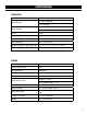
SPECIFICATIONS GENERATOR Model Number Rated Wattage Surge Wattage DF475X Gasoline: 3800 Watts LPG: 3500 Watts Gasoline: 4750 Watts LPG: 4350 Watts Phase Single Frequency 60 Hz Rated Voltage AC: 120V/240V, DC: 12V Rated Amperage AC: 32A/16A, DC: 8A Product Dimensions (With Wheel Kit) 23.2 in. x 17.5 in. x 18.5 in. (L x W x H) Product Net Weight (With Wheel Kit) 105.
INTRODUCTION Thanks for purchasing the WEN 4750-Watt Portable Generator. Refer to the illustration below for the location of the serial number on the specifications label. Record the generator information in the spaces provided below. If assistance for information or service is required, please contact customer service by calling 1-800-232-1195, M-F 8-5 CST; you will be asked to provide the following generator information when calling.
GENERAL SAFETY RULES WARNING! Read all safety warnings and all instructions. Failure to follow the warnings and instructions may result in electric shock, fire and/or serious injury. Safety is a combination of common sense, staying alert and knowing how your item works. The term “power tool” in the warnings refers to your mains-operated (corded) power tool or battery-operated (cordless) power tool. SAVE THESE SAFETY INSTRUCTIONS. WORK AREA SAFETY 1. Keep work area clean and well lit.
GENERAL SAFETY RULES WARNING! Read all safety warnings and all instructions. Failure to follow the warnings and instructions may result in electric shock, fire and/or serious injury. Safety is a combination of common sense, staying alert and knowing how your item works. The term “power tool” in the warnings refers to your mains-operated (corded) power tool or battery-operated (cordless) power tool. SAVE THESE SAFETY INSTRUCTIONS. 7.
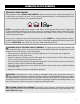
GENERATOR SAFETY WARNINGS DANGER! CARBON MONOXIDE Using a generator indoors CAN KILL YOU IN MINUTES. Generator exhaust contains carbon monoxide (CO). This is a poison gas you cannot see or smell. If you can smell the generator exhaust, you are breathing CO. But even if you cannot smell the exhaust, you could be breathing CO. NEVER use a generator inside homes, garages, crawl spaces, or other partially enclosed areas. Deadly levels of carbon monoxide can build up in these areas.
GENERATOR SAFETY WARNINGS WARNING! Do not let comfort or familiarity with the product replace strict adherence to product safety rules. Failure to follow the safety instructions may result in serious personal injury. OPERATING ENVIRONMENT 1. Using a generator indoors can kill you in minutes. Only use a generator outside and far away from windows, doors and vents. 2. Do not smoke near the generator. 3. Do not operate near open flame, heat, or flammable materials.
GENERATOR SAFETY WARNINGS WARNING! Do not let comfort or familiarity with the product replace strict adherence to product safety rules. Failure to follow the safety instructions may result in serious personal injury. TO MAXIMIZE THE LIFESPAN OF YOUR GENERATOR: We recommend running your generator at least once a month for 20 to 30 minutes. Start the generator according to the instructions and plug a small load in to make sure the outlet is producing electricity.
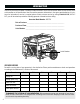
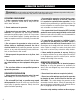
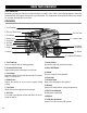
KNOW YOUR GENERATOR TOOL PURPOSE Generators provide you with power when and where you need it most. Refer to the following diagrams to become familiarized with all the parts and controls of your Generator. The components will be referred to later in the manual for assembly and operation instructions. GENERATOR 1. Fuel Tank Cap 2. Pressure Relief Valve 10. Fuel Tank 3. Fuel Gauge 11. Control Panel 4. Choke Lever 5. Fuel Valve 6. Air Filter 7. Recoil Starter 8. Engine 12. Battery 13.
KNOW YOUR GENERATOR CONTROL PANEL 1 2 3 11 10 4 5 6 9 8 7 before s t ar ting Maintenance Rules 1. Drain the carburetor after each use. 2. Run generator at least once a month for 15 minutes. 3. Empty gas tank and disconnect LPG tank before storing for extended periods. 1. Fuel Selector Switch Turn the dial to easily switch between gasoline or LPG before operation. 7. AC 120/240V 30A NEMA L14-30R Receptacle Connect electrical devices that run on 120V/240V, 60 Hz, single phase, AC current. 2.
UNPACKING & PACKING LIST UNPACKING With the help of a friend or trustworthy foe, such as one of your in-laws, carefully remove the generator from the packaging and place it on a sturdy, flat surface. Make sure to take out all contents and accessories. Do not discard the packaging until everything is removed. Check the packing list below to make sure you have all of the parts and accessories.
ASSEMBLY & ADJUSTMENTS TO INSTALL THE FEET: Slide two M6x40 bolts (32) through the foot support assembly (43) and the generator frame. Tighten with M6 nuts (45). Repeat for the other foot. TO INSTALL THE WHEELS: NOTE: Connecting/disconnecting the battery’s negative terminal requires removing the right wheel. For your convenience, the battery’s negative terminal has been pre-connected. Before installing the wheels, verify that the negative terminal of the battery has been connected securely (see p.
GENERATOR PREPARATION The following section describes the necessary steps to prepare the generator for use. If you are unsure about how to perform any of the steps please call 1-800-232-1195 (M-F 8-5 CST) for customer service. Failure to perform these steps properly can damage the generator or shorten its life. STEP 1 - ADD/CHECK OIL The generator is shipped without oil. User must add the proper amount of oil before operating the generator for the first time.
GENERATOR PREPARATION TO CHECK OIL LEVEL (before every subsequent start): Fig. 5 1. Place the generator on a level surface. Make sure the engine is OFF before adding or checking oil. 2. Remove and wipe the dipstick with a clean rag. Upper Limit 3. Insert the dipstick into the oil fill without screwing it in. Remove the dipstick to check the oil mark. 4.
GENERATOR PREPARATION TO ADD GASOLINE: 1. Place the generator on a level surface. Make sure the engine is OFF before adding or checking the fuel. Fuel Fuel Cap Gauge Fig. 6 2. Unscrew the fuel cap (Fig. 6) and set it aside. The fuel cap may be tight and hard to unscrew. 3. Slowly add unleaded gasoline to the fuel tank. Be careful not to overfill. Reinstall fuel cap and wipe clean any spilled gasoline with a dry cloth. NOTE: Do not fill the fuel tank to the very top.
GENERATOR PREPARATION FUEL OPTION B: LIQUID PETROLEUM GAS (LPG) (CONT.) NOTE: LPG regulator inlet pressure is approximately 30 PSI at 0 °F, and 218 PSI at 100 °F. • You can use LPG tanks with Type 1, right hand Acme threads with this generator. Verify that the qualification date on tank has not expired. Do not use rusted or damaged cylinders. • All new cylinders must be purged of air and moisture prior to filling. Used cylinders that have not been plugged or kept closed must also be purged.
GENERATOR PREPARATION STEP 3 - CONNECT THE BATTERY WARNING! BATTERY GIVES OFF EXPLOSIVE HYDROGEN GAS. • Keep battery away from spark, flame, or cigarette. • Do not connect or disconnect battery while generator is running. • Service or use battery only in well ventilated areas. WARNING! Battery contains sulfuric acid. Battery acid is poisonous. Tilting the generator with the battery installed can cause battery acid to spill. • Wear protective clothing and eye wear when servicing battery.
GENERATOR PREPARATION STEP 4 - GROUND THE GENERATOR Fig. 10 To reduce the risk of electric shock and to maximize safety, the generator should be properly grounded. Ground the generator by tightening the grounding nut on the front control panel (Fig. 10) against a grounding wire. A generally acceptable grounding wire is a No. 12 AWG (American Wire Gauge) stranded copper wire. This grounding wire should be connected at the other end to a copper, brass, or steel-grounding rod that is driven into the earth.
STARTING THE GENERATOR Before starting the generator, make sure you have read and performed the steps in the “Generator Preparation” section of this manual. If you are unsure about how to perform any of the steps in this manual please call 1-800-232-1195 (M-F 8-5 CST) for customer service. DANGER: CARBON MONOXIDE Using a generator indoors CAN KILL YOU IN MINUTES. Generator exhaust contains carbon monoxide (CO). This is a poison gas you cannot see or smell.
STARTING THE GENERATOR BEFORE STARTING THE GENERATOR Fig. 11 1. Verify that the generator is outside on a dry, level surface. Allow at least two feet of clearance on all sides of the generator. 2. To maximize safety, check that the generator is properly grounded (see “Ground the Generator”). 3. Check there is sufficient level of oil in the crankcase. Add oil if necessary (see “Add/check Oil”). 4. Verify the fuel selection dial is turned to the desired fuel.
USING YOUR GENERATOR CALCULATING THE WATTAGE OF YOUR DEVICE(S) Connect electrical devices running on AC current according to their wattage requirements. Calculate the total running wattage and starting wattage of the device(s) you wish to connect, and MAKE SURE that they are within the capacity of your generator and the capacity of each individual outlet.
USING YOUR GENERATOR CALCULATING THE WATTAGE OF YOUR DEVICE(S) - CONTINUED The chart below serves as a reference for the estimated wattage requirements of common electrical devices. However, do not solely rely on this chart - all electronics and appliances are built differently. Always check the wattage listed on the electrical device before consulting this chart.
USING YOUR GENERATOR CONNECTING ELECTRICAL DEVICES CAUTION: Become familiar with the functions and capacity of each component on the control panel (page 11) before connecting electrical devices. Do not overload generator or individual panel receptacles. Do not connect 50Hz or 3-phase loads to the generator. Follow the steps below to properly connect your device(s) to the generator: 1.
USING YOUR GENERATOR CO SENSOR INFORMATION The CO Watchdog carbon monoxide monitoring system (Fig. 13) measures the accumulation of poisonous CO gas while the generator is running. If the level of CO gas gets too high, the CO Watchdog system will automatically shut down the generator. This system is not a substitute for an indoor CO alarm. Whenever the CO Watchdog system shuts down the generator, one of the LED lights on the generator control panel (Fig.
USING YOUR GENERATOR CHANGING FUELS 1. Before changing the fuel source, make sure the generator is turned off or running under half-load. Do not change fuel when generator is over half-load. 2. If switching from LPG to gasoline, turn off the LPG tank valve and disconnect LPG fuel tank from generator. Then turn ON the fuel valve. If switching from gasoline to LPG, turn off the fuel valve. Then follow the LPG connecting procedure in section “FUEL OPTION B: Liquid petroleum gas (LPG)”. 3.
MAINTENANCE RECOMMENDED MAINTENANCE SCHEDULE Proper routine maintenance of the generator will help prolong the life of the machine. Please perform maintenance checks and operations according to the maintenance schedule below, Table 4. If there are any questions about the maintenance procedures listed in this manual, please contact customer service at 1-800-232-1195 (M-F 8-5 CST), or email techsupport@wenproducts.com. WARNING! Never perform maintenance operations while the generator is running.
MAINTENANCE CLEANING THE GENERATOR Keep the generator clean to prevent improper operation or machine damage from dirt and debris. Inspect all ventilation openings on the generator. These openings must be kept clean and unobstructed. If the generator becomes dirty, use a damp cloth to wipe exterior surfaces. Use a soft bristle brush to loosen dirt and oil and use a vacuum to pick up loose dirt. Use low pressure air (not to exceed 25 PSI) to blow away dirt.
MAINTENANCE CHECKING/ADDING OIL Check the oil level before each use and every 8 hours of operation. The oil capacity of the generator engine is 20.3 fl. ounces. Add oil when the oil level is low. For proper type and weight of oil refer to “add oil” portion of the “Generator Preparation” section. This is a critical step for proper engine starting. The generator is equipped with an automatic shutoff to protect it from running on low oil. To check the oil level and add oil: 1.
N MAINTENANCE M AIR FILTER MAINTENANCE L Check every 50 hours of operation (refer to Recommended Maintenance Schedule). Routine maintenance of the air filter helps maintain proper airflow to the carburetor. Occasionally check that the air filter is free of excessive dirt. Clean air filter more frequently in dirty or dusty conditions K To inspect and clean the air filter: 1. Remove the air filter cover (Fig. 17) by undoing the clasps at the top and bottom of the air filter cover. Fig. 17 J H 2.
MAINTENANCE SPARK PLUG MAINTENANCE Refer to Recommended Maintenance Schedule for maintaining the spark plug. The spark plug is important for proper engine operation. Check the spark plug regularly to maintain proper engine operation. A good spark plug should be intact, free of deposits, and properly gapped. To inspect or replace the spark plug: 1. Pull on the spark plug boot to remove it (Fig. 19). Be careful not to tear insulation or wire. Fig. 19 Spark Plug Boot 2.
MAINTENANCE BATTERY MAINTENANCE/STORAGE The battery (part no. DF475-041) shipped with the generator has been fully charged. The battery will receive charge when the engine is running. Remember to run the generator once a month for 20-30 minutes to charge the battery. A charged battery will allow you to start the generator using the electric start switch during your next time of need.
MAINTENANCE TESTING THE GFCI OUTLETS Test the GFCI outlets monthly. The GFCI outlets have two buttons between the receptacles (refer to Fig. 22): • RESET (upper) • TEST (lower) Fig. 22 To test: 1. Start the generator according to the instructions in this manual. Wait a few minutes for the generator to stabilize its speed and voltage output. 2. Press the RESET button on the GFCI outlet (Fig. 22). 3. Connect a device to the outlet and turn it ON. 4.
TRANSPORTATION & STORAGE TRANSPORTING THE GENERATOR To prevent fuel spillage when transporting, be sure to perform the following to your generator: 1. Tighten the fuel cap and make sure the fuel valve is turned OFF. 2. Make sure the engine switch is in the OFF position. 3. Drain the fuel tank if possible (see “Draining the Fuel Tank”). 4. Keep the generator upright.
TROUBLESHOOTING GUIDE WARNING! Stop using the generator immediately if any of the following problems occur or risk serious personal injury. If you have any questions, please contact customer service at 1-800-232-1195 (M-F 8-5 CST), or email techsupport@wenproducts.com. PROBLEM Engine will not start. Engine runs but there is no electrical output from the GFCI outlets. Engine runs but there is no electrical output whatsoever. Generator runs but does not support all electrical devices connected.
Neutral WIRING DIAGRAM 36
EXPLODED VIEW & PARTS LIST GENERATOR 37
EXPLODED VIEW & PARTS LIST GENERATOR 38 No. Part No. Description Qty. No. Part No. Description Qty. 1 DF475X-001 Alternator Assembly 1 29 DF475X-029ASM Control Panel Assembly 1.1 DF475-001.1 Carbon Brush Assembly 1 1 29.1 DF475-029.1 Ignition Switch 1 2 DF475-002 Motor Stand 1 N.P. P55340 Starter Key (set of 2) 1 3 DF475-003 Switch Dial Assembly 1 29.2 DF475-029.2 DC Receptacle, 12V 1 4 DF475-004 Hexagon Pattern Pan Head Screws M6x12 1 29.3 DF475-029.
EXPLODED VIEW & PARTS LIST GENERATOR No. Part No. Description Qty. No. Part No. Description Qty.
EXPLODED VIEW & PARTS LIST ENGINE 40
EXPLODED VIEW & PARTS LIST ENGINE No. Part No. Description Qty. No. Part No. Description Qty. 1 DF475-101 Crankcase 1 28 DF475-128 Rotator 1 2 DF475-102 Ball Bearing 2 29 DF475-129 Carburetor Stud Bolt 2 3 DF475-103 Oil Seal 2 30 DF475-130 Stud Bolt 2 4 DF475-104 Governor Assembly 1 31 DF475-131 Carburetor Assembly 1 5 DF475-105 Governor Arm Shaft 1 32 DF475X-132 Fuel Line 1 6 DF475-106 Governor Arm Shaft Washer 1 33 DF475-133 Fuel Line Clip Ø7.
EXPLODED VIEW & PARTS LIST ENGINE 42 No. Part No. Description Qty. No. Part No. Description Qty.
WARRANTY STATEMENT WEN Products is committed to building tools that are dependable for years. Our warranties are consistent with this commitment and our dedication to quality. LIMITED WARRANTY OF WEN PRODUCTS FOR HOME USE GREAT LAKES TECHNOLOGIES, LLC (“Seller”) warrants to the original purchaser only, that all WEN consumer power tools will be free from defects in material or workmanship during personal use for a period of two (2) years from date fessional or commercial use.
THANKS FOR REMEMBERING V. 2021.10.