MODEL DF875iX 8750-WATT INVERTER GENERATOR Instruction Manual NEED HELP? CONTACT US! Have product questions? Need technical support? Please feel free to contact us: 1-800-232-1195 (M-F 8AM-5PM CST) TECHSUPPORT@WENPRODUCTS.COM IMPORTANT: Your new tool has been engineered and manufactured to WEN’s highest standards for dependability, ease of operation, and operator safety. When properly cared for, this product will supply you years of rugged, trouble-free performance.
CONTENTS WELCOME 3 Specifications.................................................................................................... 3 Introduction...................................................................................................... 4 SAFETY 5 General Safety Rules......................................................................................... 5 Generator Safety Warnings...............................................................................
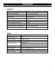
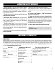
SPECIFICATIONS GENERATOR Model Number DF875iX Surge (Starting) Wattage Gas: 8750W LPG: 7800W Rated (Running) Wattage Gas: 7000W LPG: 6300W Rated Voltage 120V / 240V AC Phase Single Frequency 60 Hz Product Weight With Wheel Kit 140 lbs Product Weight Without Wheel Kit 134.5 lbs Product Dimensions With Wheel Kit 26.8 in. x 26.4 in. x 23.2 in. Product Dimensions Without Wheel Kit 23.8 in. x 20.2 in. x 21.1 in.
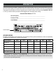
INTRODUCTION Thanks for purchasing the WEN 8750-Watt Dual Fuel Inverter Generator. Refer to the illustration below for the location of the serial number on the specifications label. Record the generator information in the spaces provided below. If assistance for information or service is required, please contact customer service by calling 1-800-232-1195, M-F 8-5 CST; you will be asked to provide the following generator information when calling.
GENERAL SAFETY RULES WARNING! Read all safety warnings and all instructions. Failure to follow the warnings and instructions may result in electric shock, fire and/or serious injury. Safety is a combination of common sense, staying alert and knowing how your item works. The term “power tool” in the warnings refers to your mains-operated (corded) power tool or battery-operated (cordless) power tool. SAVE THESE SAFETY INSTRUCTIONS. WORK AREA SAFETY 1. Keep work area clean and well lit.
GENERAL SAFETY RULES WARNING! Read all safety warnings and all instructions. Failure to follow the warnings and instructions may result in electric shock, fire and/or serious injury. Safety is a combination of common sense, staying alert and knowing how your item works. The term “power tool” in the warnings refers to your mains-operated (corded) power tool or battery-operated (cordless) power tool. SAVE THESE SAFETY INSTRUCTIONS. 7.
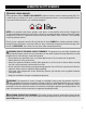
GENERATOR SAFETY WARNINGS DANGER! CARBON MONOXIDE Using a generator indoors CAN KILL YOU IN MINUTES. Generator exhaust contains carbon monoxide (CO). This is a poison gas you cannot see or smell. If you can smell the generator exhaust, you are breathing CO. But even if you cannot smell the exhaust, you could be breathing CO. NEVER use a generator inside homes, garages, crawl spaces, or other partially enclosed areas. Deadly levels of carbon monoxide can build up in these areas.
GENERATOR SAFETY WARNINGS WARNING! Do not let comfort or familiarity with the product replace strict adherence to product safety rules. Failure to follow the safety instructions may result in serious personal injury. OPERATING ENVIRONMENT 1. Using a generator indoors can kill you in minutes. Only use a generator outside and far away from windows, doors and vents. 2. Do not smoke near the generator. 3. Do not operate near open flame, heat, or flammable materials.
GENERATOR SAFETY WARNINGS 4. Allow generator to run for several minutes before connecting electrical devices. Do not start or stop engine with electrical devices plugged in to the receptacles. Failure to do so could damage the generator and/or connected electrical devices. 5. Do not turn on electrical devices until after they are connected to the generator. 6. Generators vibrate in normal use.
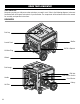
KNOW YOUR GENERATOR TOOL PURPOSE Generators provide you with power when and where you need it most. Refer to the following diagrams to become familiarized with all the parts and controls of your Generator. The components will be referred to later in the manual for assembly and operation instructions.
KNOW YOUR GENERATOR CONTROL PANEL 1 2 3 14 13 4 5 12 6 11 1. CO WATCHDOG Carbon Monoxide Monitor Measures the accumulation of poisonous CO gas while the generator is running. If the level of CO gas gets too high, the CO Watchdog system will automatically shut down the generator. See p. 31 for more information. 2.
ASSEMBLY & ADJUSTMENTS HIGH ALTITUDE OPERATION ABOVE 3000 FEET The fuel system on this generator may be affected by operation at high altitudes. Proper operation can be ensured by installing an altitude kit at altitudes higher than 3000 feet above sea level. At elevations above 8000 feet, the engine may experience a decrease in performance, even with the proper altitude kit.
ASSEMBLY & ADJUSTMENTS WARNING! Do not turn on the generator until it is fully assembled according to the instructions. Read through and become familiarized with the following procedures of handling and adjusting your tool. Failure to follow the safety instructions may result in serious personal injury. • Never use the handle as a lifting point to support the entire weight of the generator. Only use the handle to pull the generator with the help of the wheels. • Use caution when collapsing the handle.
GENERATOR PREPARATION The following section describes the necessary steps to prepare the generator for use. If you are unsure about how to perform any of the steps please call 1-800-232-1195 (M-F 8-5 CST) for customer service. Failure to perform these steps properly can damage the generator or shorten its life. STEP 1 - ADD/CHECK OIL The generator is shipped without oil. User must add the proper amount of oil before operating the generator for the first time.
GENERATOR PREPARATION TO CHECK OIL LEVEL (before every subsequent start): Fig. 5 1. Place the generator on a level surface. Make sure the engine is OFF before adding or checking oil. 2. Remove and wipe the dipstick with a clean rag. Upper Limit 3. Insert the dipstick into the oil fill without screwing it in. Remove the dipstick to check the oil mark. 4.
GENERATOR PREPARATION TO ADD GASOLINE: 1. Place the generator on a level surface. Make sure the engine is OFF before adding or checking the fuel. Fuel Gauge Fig. 6 Fuel Cap 2. Unscrew the fuel cap (Fig. 6) and set it aside. The fuel cap may be tight and hard to unscrew. 3. Slowly add unleaded gasoline to the fuel tank. Be careful not to overfill. Reinstall fuel cap and wipe clean any spilled gasoline with a dry cloth. NOTE: Do not fill the fuel tank to the very top.
GENERATOR PREPARATION FUEL OPTION B: LIQUID PETROLEUM GAS (LPG) (CONT.) 4. Turn the LPG tank valve ON (Fig. 9) and check for leaks by spraying soapy water to check connections. If bubbles appear, become larger in size, or increase in number, a leak exists. This MUST be corrected before using generator. Contact WEN customer service at 1-800-2321195, M-F 8-5 CST, or email techsupport@wenproducts.com for assistance. Fig.
GENERATOR PREPARATION ABOUT THE BATTERY (CONT.) 4. AVOID DAMAGE AND SHOCKS. Immediately replace batteries that have been dropped from a height of more than one meter (3 feet) or those that have been exposed to violent shocks, even if the housing of the battery appears to be undamaged. The battery cells inside the battery may have suffered serious damage. In such instances, please read the waste disposal information on p. 31 for proper battery disposal. 5. DO NOT CRUSH, DROP OR DAMAGE BATTERY.
STARTING THE GENERATOR Before starting the generator, make sure you have read and performed the steps in the “Generator Preparation” section of this manual. If you are unsure about how to perform any of the steps in this manual please call 1-800-232-1195 (M-F 8-5 CST) for customer service. DANGER: CARBON MONOXIDE Using a generator indoors CAN KILL YOU IN MINUTES. Generator exhaust contains carbon monoxide (CO). This is a poison gas you cannot see or smell.
STARTING THE GENERATOR BEFORE STARTING THE GENERATOR 1. Verify that the generator is outside on a dry, level surface. Allow at least two feet of clearance on all sides of the generator. 2 Fig. 11 2. To maximize safety, check that the generator is properly grounded. Refer to "Step 4 - Ground The Generator." 3. Check that there is a sufficient level of oil in the crankcase. Add oil if necessary. Refer to "Step 1 - Add/Check Oil." 4. If using gasoline, make sure there is enough gasoline in the fuel tank.
STARTING THE GENERATOR STARTING THE GENERATOR (GASOLINE) CONT. a. To start the engine using the electric starter: b. To start the engine using the recoil starter: i. Make sure the battery is properly connected. If the battery is dead or not connected, the generator will not start. i. Move the choke lever (Fig. 14 - 1) left to the closed position. If the engine is warm, move the choke lever right to the open position. ii. Press the engine start/stop button (Fig. 13 - 1) once. Do not hold it down. ii.
STARTING THE GENERATOR STARTING THE GENERATOR (PROPANE) 2 1. Turn the ECO-mode switch (Fig. 15 - 1) to OFF during starting. Fig. 15 2. Turn the battery switch (Fig. 15 - 2) to ON during starting. 3. Ensure that all electrical devices are disconnected from the generator. 4. Turn the fuel selector switch (Fig. 16 - 1) to the “PROPANE” position (left). 1 5.
STARTING THE GENERATOR USING THE REMOTE-START FUNCTION Your generator comes with a remote-start function, enabling you to (what else?) start your generator remotely. Your generator and the included remote have been paired at the factory, and you can use the remote immediately. NOTE: In order for the remote start function to work properly, you must be within 164 ft (50 m) of the generator.
STARTING THE GENERATOR STORING THE REMOTE We recommend clasping your remote to the loops on the USB cover on the panel for easy access. 1 Fig. 17 PAIRING THE REMOTE AND GENERATOR 1. Make sure the battery is connected and charged, and the battery switch on the panel is set to ON. 2. Press the remote pairing button (Fig. 17 - 1) on the control panel once. 3. The engine start/stop button will flash red once. 4.
STARTING THE GENERATOR STANDBY MODE Once the generator is shut down, the generator’s remote control function will stay in standby mode while the battery switch is ON. In standby mode, the generator can be started using the remote. The engine start/stop button will blink green once every 2 seconds to remind you that the generator is in standby mode.
USING THE GENERATOR CALCULATING THE WATTAGE OF YOUR DEVICE(S) Connect electrical devices running on AC current according to their wattage requirements. Calculate the total running wattage and starting wattage of the device(s) you wish to connect, and MAKE SURE that they are within the capacity of your generator and the capacity of each individual outlet.
USING THE GENERATOR CALCULATING THE WATTAGE OF YOUR DEVICE(S) - CONTINUED The chart below serves as a reference for the estimated wattage requirements of common electrical devices. However, do not solely rely on this chart - all electronics and appliances are built differently. Always check the wattage listed on the electrical device before consulting this chart.
USING THE GENERATOR CONNECTING ELECTRICAL DEVICES 1. Before connecting electrical devices, allow the generator to run for a few minutes to stabilize the speed and voltage output. 2. Select the device with the highest wattage, and make sure it is turned off. Plug the device into the matching generator outlet and then turn the device on. Allow the engine to stabilize. 3. Repeat step 2 to plug in each additional device. Do not attempt to plug in or start multiple devices at the same time.
USING THE GENERATOR LIGHT GREEN (POWER INDICATOR) MEANING RED (OVERLOAD) RESOLUTION ON OFF Generator output is normal. No action needed. OFF Flashes 1x, repeating every 3 sec Voltage at alternator is too low. No electrical output. Check for loose connections. Call 1-800-232-1195 for assistance. OFF Flashes 2x, repeating every 3 sec Engine speed is too low. No electrical output. Check carburetor and stepper motor. Ensure Eco-Mode is OFF.
USING THE GENERATOR SWITCHING FUELS To maximize your generator's lifespan, we recommend removing all loads from the generator before switching between gasoline and LPG. If this is not possible, reduce loads as much as possible in order to ensure a smooth switch. Your generator is rated to handle a higher load when running on gasoline than on LPG, so keep this in mind when planning your fuel usage. To switch fuels: 1. Make sure you have enough gasoline or propane.
USING THE GENERATOR CO SENSOR INFORMATION The CO Watchdog carbon monoxide monitoring system (Fig. 19 - 1) measures the accumulation of poisonous CO gas while the generator is running. If the level of CO gas gets too high, the CO Watchdog system will automatically shut down the generator. This system is not a substitute for an indoor CO alarm. Whenever the CO Watchdog system shuts down the generator, the LED on the generator control panel (Fig.
SHUTTING OFF THE GENERATOR CAUTION! Unplugging running devices can cause damage to the generator. Never stop the engine with electrical devices connected and running. WARNING! Allow the generator to cool down before touching areas that become hot during use. CAUTION! Allowing gasoline to sit in the fuel tank for long periods of time can make it difficult to start the generator in the future. Never store the generator for extended periods of time (over 2 months) with fuel in the fuel tank.
MAINTENANCE RECOMMENDED MAINTENANCE SCHEDULE Proper routine maintenance of the generator will help prolong the life of the machine. Please perform maintenance checks and operations according to the maintenance schedule below, Table 4. If there are any questions about the maintenance procedures listed in this manual, please contact customer service at 1-800-232-1195 (M-F 8-5 CST), or email techsupport@wenproducts.com. WARNING! Never perform maintenance operations while the generator is running.
MAINTENANCE CLEANING YOUR GENERATOR Keep the generator clean to prevent improper operation or machine damage from dirt and debris. Inspect all ventilation openings on the generator. These openings must be kept clean and unobstructed. If the generator becomes dirty, use a damp cloth to wipe exterior surfaces. Use a soft bristle brush to loosen dirt and oil and use a vacuum to pick up loose dirt. Use low pressure air (not to exceed 25 PSI) to blow away dirt.
MAINTENANCE DRAINING THE CARBURETOR Fig. 21 Drain the carburetor after every use and before storing the generator (refer to Table 4). Draining the carburetor can help prevent build-up and blockages caused by stagnant fuel inside of the carburetor. 1 1. Prepare an approved gasoline-storage container under the carburetor to collect the drained fuel. Close fuel valve. 2. The carburetor can be accessed from the backside of the generator between the engine and the air filter.
MAINTENANCE INSPECTING/CLEANING THE SPARK ARRESTOR Fig. 23 Inspect and clean the spark arrestor every 100 hours of operation (refer to Table 4). The spark arrestor is located outside the muffler, which gets very hot during operation. Allow the engine to cool completely before servicing the spark arrestor. 1. Remove the two bolts that secure the spark arrestor to the muffler. See Fig. 23. 2. Remove the spark arrestor screen. 3.
MAINTENANCE 5. Measure the plug gap with a spark plug gap gauge. The gap should be 0.7 to 0.8 mm (0.028-0.031 in). Carefully adjust the gap if necessary. See Fig. 24. Fig. 24 0.7 - 0.8mm 6. Screw the spark plug back into the spark plug hole using the spark plug wrench. Do not over-tighten spark plug. Recommended tightening of the spark plug is ½ to ¾ of a turn (15 ft-lb torque/20.33 Nm) after the spark plug gasket contacts the spark plug hole. 7. Reinstall the spark plug boot over the spark plug.
MAINTENANCE BATTERY MAINTENANCE/STORAGE The battery will receive charge when the engine is running. Remember to run the generator once a month for 20-30 minutes to charge the battery. A charged battery will allow you to start the generator during your next time of need. IMPORTANT! If you do not plan to use the generator for a long period of time, we recommend DISCONNECTING the negative battery cable from the battery to protect the battery from losing charge.
TRANSPORTATION & STORAGE TRANSPORTING THE GENERATOR To prevent fuel spillage when transporting, be sure to perform the following: 1. Tighten the fuel cap and turn the fuel valve to the OFF position. 2. Flip the engine switch to the STOP position. 3. Drain the fuel tank if possible. Refer to "Draining The Fuel Tank." 4. Keep the generator upright. Never place the generator on its side or upside down - doing so could damage the internal components of the generator and make it difficult to start.
TROUBLESHOOTING GUIDE WARNING! Stop using the generator immediately if any of the following problems occur or risk serious personal injury. If you have any questions, please contact customer service at 1-800-232-1195 (M-F 8-5 CST), or email techsupport@wenproducts.com. PROBLEM Engine will not start. Engine will not start (remote start). POSSIBLE CAUSE 1. Fuel selector switch is in wrong position. 1. Set fuel selector switch to match fuel being used. 2. Battery switch is set to OFF (0). 2.
TROUBLESHOOTING GUIDE WARNING! Stop using the generator immediately if any of the following problems occur or risk serious personal injury. If you have any questions, please contact customer service at 1-800-232-1195 (M-F 8-5 CST), or email techsupport@wenproducts.com. PROBLEM Generator runs but does not support all electrical devices connected. POSSIBLE CAUSE 1. Generator is overloaded. 1. Turn off and unplug electrical device(s).
WIRING DIAGRAM 42
EXPLODED VIEW & PARTS LIST NOTE: Replacement parts can be purchased from wenproducts.com, or by calling our customer service at 1-(800) 232-1195, M-F 8-5 CST. Parts and accessories that wear down over the course of normal use are not covered by the two-year warranty. Not all parts may be available for purchase.
EXPLODED VIEW & PARTS LIST ASSEMBLY 3 - CRANKCASE COVER 6 5 7 5 3 2 4 4 3 2 7 No. Part No. Description Qty. 3-1 GN875i-0301 Crankcase Cover Gasket 1 3-2 GN875i-0302 Bearing, 6202P6 1 3-3 GN625i-0304 Oil Dipstick Subassembly 1 3-4 GN875i-0304 Pin 3-5 GN875i-0305 3-6 3-7 1 No. Part No. Description Qty.
EXPLODED VIEW & PARTS LIST ASSEMBLY 6 - RECOIL STARTER ASSEMBLY 7 - SHROUD, LOWER SHIELD 4 2 1 3 1 3 2 No. Part No. Description Qty. No. Part No. Description Qty. 7-1 56200-1202 Bolt, M6x12 5 6-1 GN625i-0701 Bolt, M6x20 3 7-2 GN625i-0802 Retaining Ring 1 6-2 GN875i-0602 Recoil Starter Assembly 1 7-3 GN875i-0703 Shroud 1 6-3 GN625i-0703 Flat Washer, 6mm 3 7-4 GN400i-0703 Clip 1 ASSEMBLY 8 - CARBURETOR 2 5 3 6 1 8 4 7 7 No. Part No. Description Qty.
EXPLODED VIEW & PARTS LIST ASSEMBLY 9 - FLYWHEEL, IMPELLER, STARTER PULLEY ASSEMBLY 10 - AIR FILTER 2 7 6 3 4 2 13 5 9 46 8 10 11 1 7 3 15 1 14 12 No. Part No. 10-1 DF875iX-1001 Description Qty. Air Filter Assembly 1 No. Part No. Description Qty. 9-1 DF875iX-0901 Rotor 1 9-2 DF875iX-0902 Stator 1 9-3 GN625i-0214 Wiring Clamp 1 9-4 GN875i-0904 Bolt, M5x10 1 9-5 GN625i-1101 Flywheel Nut, M161.
EXPLODED VIEW & PARTS LIST ASSEMBLY 12 - FUEL TANK No. Part No. Description Qty. No. Part No. Description Qty.
EXPLODED VIEW & PARTS LIST ASSEMBLY 13 - FRAME 10 12 11 33 33 27 40 35 39 41 22 23 25 38 13 24 16 15 36 37 8 3 6 30 17 34 5 4 1 9 2 7 14 31 32 18 Part No. Description Qty. 13-17 56380i-1304 Battery (Li-ion, 12V, 1.
EXPLODED VIEW & PARTS LIST ASSEMBLY 14 - CONTROL PANEL 7 4 3 4 3 3 4 3 4 2 29 2 8 12 10 10 11 23 9 30 26 24 2 20 13 5 28 27 22 19 14 25 31 1516 17 18 21 6 6 1 6 6 6 6 No. Part No. Description Qty. No. Part No. Description Qty.
EXPLODED VIEW & PARTS LIST ASSEMBLY 15 - WHEEL AND HANDLE 3 1 4 5 6 12 7 13 2 12 13 12 16 13 13 14 15 12 16 13 14 15 8 17 50 13 11 10 11 9 10 8 18 9 18 No. Part No. Description Qty. No. Part No. Description Qty.
WARRANTY STATEMENT WEN Products is committed to building tools that are dependable for years. Our warranties are consistent with this commitment and our dedication to quality. LIMITED WARRANTY OF WEN PRODUCTS FOR HOME USE GREAT LAKES TECHNOLOGIES, LLC (“Seller”) warrants to the original purchaser only, that all WEN consumer power tools will be free from defects in material or workmanship during personal use for a period of two (2) years from date fessional or commercial use.
THANKS FOR REMEMBERING V. 2022.03.