
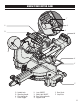
Use and Care Manual

1312
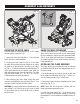
Fig. 4 Fig. 5
ASSEMBLY & ADJUSTMENTS
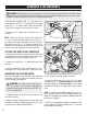
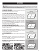
ADJUSTING THE MITER ANGLE
The miter table can be adjusted from 0° to 45° to both
left and right to create miter cuts.
1. Loosen the miter lock knob (Fig. 4 - 5) by turning it
one or two turns counterclockwise.
2. Pull up on the miter stop lever (Fig. 4 - 4) to unlock
the table. While holding the miter stop lever up, adjust
the table to the desired angle. The miter scale indica-
tor (Fig. 4 - 3) will point towards the selected angle. To
make micro adjustments to a specific angle, rotate the
table while pulling up on the miter stop lever. The miter
table has positive stops at 0°, 15°, 22.5°, 30°, and 45°
in both directions for quick adjustments.
3. After selecting your miter angle, release the miter
stop lever and tighten the miter lock knob (Fig. 4 - 5) by
turning it clockwise to lock the table in place.
WARNING: Be sure the miter table is locked in place be-
fore making a cut. Failure to do so can cause the table
to move during the cut, which could result in serious
personal injury.
USING THE TABLE EXTENSIONS
The table extensions (Fig. 4 - 1) come pre-installed on
either side of your miter saw and serve as extra support
for your workpiece. Loosen the table extension knobs
(Fig. 4 - 2) to adjust their positioning. The stop plate on
each table extension can be raised to quickly and easily
make repeated cuts.
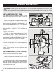
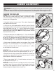
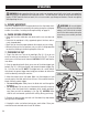
INSTALLING THE CLAMP ASSEMBLY
The clamp comes pre-assembled and can be mounted
on the left or right side of the saw depending on the cut-
ting task at hand.
1. Locate the hole for the clamp on the left or right side
of the miter saw behind the fence (Fig. 5 - arrows). In-
sert the clamp assembly (Fig. 5) into the slot.
2. Secure the clamp into place by tightening the clamp
lock screw (Fig. 5 - 1).
NOTE: Check that the clamp won’t interfere with the
blade travel before operating the saw.
3. Rotate the clamp knob (Fig. 5 - 2) to move it up or
down as needed to securing the workpiece. Check that
the workpiece is secure and does not wobble before cut-
ting.
1 2
3
4
5
Clamp
Assembly
2
1