
Installation Guide

INSTALLATION OF POLE TO WORK WALL
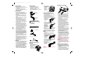
1. Install pole foot into bottom of pole. Ensure button
locks are securely snapped into holes on pole.
2. Erect Pump Jack system on firm ground. When
working on soil, plywood should be used in order
to form a solid plate under the Werner pole foot.
3. Do not install pole on top of scaffold platforms or
on roof surfaces.
4. Attach support braces to roof of structure to be
worked on using at least four screws with a
minimum holding strength equivalent to 1/4" x 3"
type AB screws (See Figure above).
5. Place pole with pump jack and work bench
assemblies on ground. Ensure rubber surface of
pole is facing down toward ground with bottom of
pole pointing toward work wall of structure (see
Figure A above) or rubber surface of pole is facing
upward with top of pole pointing toward work wall
of structure (see Figure B above).
6. Align pole assembly with support braces that were
attached to roof of structure.
7. Place scaffold platform on its side against work wall
with top surface of scaffold platform facing work wall.
8. Center scaffold platform between pole assemblies,
ensuring that a rung of the scaffold platform is
aligned with appropriate attachment point on the
pump jack (see Figure above).
9. Swing Pole upward assuring that scaffold platform
will not be further than 14" from wall. Note: It is
recommended that a rope be used to hoist pole for
any pole combination in excess of 24'. Rope should
be pulled through cross members of support brace
and used to pull top of pole up to brace. A pulley
can also be attached to support brace to aid in
hoisting pole.
10. Secure support brace to pole by latching and tight-
ening support brace pole attachment cover. Ensure
cover is tight against rubber surface of pole (see
Figure C above).
WARNING! NO WORK LOAD IS PERMITTED ON THE
PUMP JACK SYSTEM DURING THIS PROCESS
11. Secure scaffold platform to pump jack using the
supplied chain. See instruction section “Installation
of Scaffold Platforms” for details on how to secure
chain.
INSTALLATION OF SCAFFOLD PLATFORMS
1. Extend platform support of each Pump Jack to the
actual width of scaffold platform and secure in place
by tightening fasteners along the side of pump jack
platform support.
2. Scaffold platforms shall overhang supports a mini-
mum of 6 inches and a maximum of 18
inches on each end unless access is restricted to the
cantilevered end. Do not load overhang. When
platforms are lapped, ends must be overlapped a
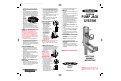
2. Slide cotter pin through
small holes located
on each end of handle
rod and bend
cotter pins to
prevent the rod
from sliding out
of position.
INSTALLATION OF PUMP JACK TO POLE
1. Place aluminum pump jack pole on ground with
rubber pad facing upward.
2. Place pump jack on ground with platform support
extending down toward ground.
3. Slide bottom end of pole (with V-shaped notch)
through top of pump jack. Ensure pump jack
platform support is facing
the ground while
pole’s rubber surface
is facing up.
4. Continue to slide pole through pump jack until pole
is advanced past lower foot lever of
pump jack causing lower foot lever to
depress into rubber
surface of pole.
Note: Lower foot
lever may need to be
disengaged to allow
pole rubber surface to
slide past.
5. Pump upper foot lever to advance pump jack until it
is approximately one foot past bottom of pole.
INSTALLATION OF WORK BENCH TO PUMP JACK
AND POLE
1. Remove nut and bolt from vertical members of
work bench.
2. With pole in same position on ground as when
pump jack was assembled, slide work bench
through top of pole with the
work bench platform
support extending up in
same direction as
pump jack pole
rubber surface.
3. Reinstall lower nut and bolt through holes in work
bench where they were removed as well as through
blue connector plates of pump jack.
4. Work bench should ride on top of
pump jack with its
platform support extending
opposite that
of pump jack.
WARNING! DO NOT STAND OR SIT ON WORK BENCH,
WHILE IN USE
SYSTEM COMPONENTS
1. Make sure you read and understand the
compatibility section of this manual.
2. Wooden poles may not be used with Werner
aluminum pump jack systems.
3. See list of system components with model numbers
below.
INSTALLATION OF LOWER FOOT LEVER
ON PUMP JACK
1. Slide lower foot lever through square
holes in bottom shackle
assembly of pump jack.
Ensure rod is
installed through square
holes on both sides
of shackle assembly.
Pump Jack -
Model# PJ-100
Work Bench -
Model# PJ-WB
6’ Pole - Model# PJ-6P
12’ Pole - Model# PJ-12P
18’ Pole - Model# PJ-18P
24’ Pole - Model# PJ-24P
Pole Connector - Model# PJ-PC
Pole Foot - Model# PJ-PF
Rigid Support Brace - Model# PJ-SBR
Foldable Support Brace - Model# PJ-SBF
WORKSITE CONDITIONS
1. Ensure worksite is free of construction debris.
2. DANGER! Metal conducts electricity. Never use near
any electrical current.
3. Inspect all power tools and extension cords to
ensure they are not damaged. Damaged tools and
cords can cause serious injury.
SPECIAL PRECAUTIONS
1. Inspect total system upon receipt and at least once
each day or before each shift when in use.
2. Never use equipment with damaged or missing
parts. Discard or contact manufacturer for repair or
replacement.
3. Follow manufacturer’s instructions when using
approved components with the Werner pump jack
system.
4. Check all parts for good condition. Lightly lubricate
moving parts occasionally.
5. Acids (hydrochloric, muriatic, etc.) and caustics
(caustic soda, trisodium phosphate, etc.) are corro-
sive to aluminum and can seriously affect its
strength. Do not expose to corrosive substances.
6. Discard any components exposed to excessive heat
or corrosive material.
7. Do not use in inclement weather or high winds.
Windy conditions require extra caution. Scaffold
platforms must be secured against wind uplift.
8. If people pass under or nearby, use safety screening
of No. 19 gage US standard wire 1/2" mesh. Cover
space between toeboard and top guard rail on all
open sides and ends of scaffold platform.
9. Provide overhead protection not more than 9 ft.
above the working plank or pedestrian walkway
where overhead hazard exists.
10. The use of fall protection equipment is always rec-
ommended. Safety codes require guard rails and
toeboards on all open sides when scaffold platform
height is 10 feet or more, and may be required at
lower heights, depending on the application and
jurisdiction. Check applicable ANSI, OSHA, state and
local codes for specific requirements.
11. If the pump jack system will be used in the absence
of a wall, a four sided guard rail system must be
used.
12. Safety belt, harness, lanyard and lifeline use must
comply with ANSI A10.8, A10.14, and A120.1, OSHA
and all applicable federal, state and local codes.
13. All equipment shall be secured to or removed from
scaffold platform. Never throw or drop tools or
materials to the ground.
COMPATIBILITY
1. Werner pump jack system components, identified in
the next section, are designed and manufactured to
be used with Alum-A-Pole Pump Jack System.
2. It is the user’s responsibility to ensure that product is
functioning properly when interchanging Werner and
Alum-A-Pole Pump Jack system components.
3. Never replace individual pieces or parts of the
system components unless supplied by Werner Co.
4. Call Werner Co. at 724-588-8600 with any questions
regarding compatibility of system components.
Cotter Pins
Pull lower foot lever
in direction of arrow
Figure C.
Pole
Attachment
Cover
Figure
A
Figure
B
Center
scaffold platform
between poles
Attach support
braces
PN63530_01 PJ Manual-eng 3/18/05 9:30 AM Page 2