
Manual


43 Owner’s Manual and Service Guide – BCG Series
COMPONENTS - ELECTRICAL
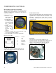
BATTERY DISCHARGE INDICATOR (BDI)
The Curtis BDI (Figure 28 shows the 24/36V version)
displays various system parameters, such as battery state-
of-charge, operating hours or maintenance status from the
Curtis motor controller.
Features include:
Attractive, easy-to-
read, 8 character dot
matrix Liquid
Crystal Display.
• 6 LEDs -five green
to indicate battery
state-of-charge and
one red to indicate
that a fault has
occurred.
• Displays hours of
use, battery state-of-
charge and
messages from the
Curtis motor
controller.
• Molded-in rear Molex style connector provides a low-
cost, rugged and reliable installation.
• Front sealed (IP65) for use in harsh environments.
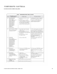
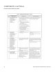
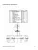
BDI Connector Pin-Out
Pin Number Function
1 N.C.
2 N.C.
3 B+ = 24V
4 B+ = 36V
5 Power In +
6 Receive
7 N.C.
8 Power In –
The BDI in 48 volt vehicles will display battery state-of-
charge and operating/ Traction hours only. Figure 29:
SPEED CONTROL PEDAL
The speed control pedal, (Figure 30) is located to the right of
the brake pedal. It controls the speed of the vehicle and is
operated with the right foot like the accelerator of an
automobile. Depressing the pedal starts the motor.
Releasing the pedal stops the motor. Reverse speed is half
of forward speed.
FIGURE 39
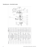
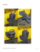
SOLENOID
The Pack Mule is provided with a SPNO DC Power
Contactor. This unit is sealed and is water resistant. The coil
voltage is matched to your particular vehicle operating
voltage, i.e. 36V or 48V. The AC option uses 24V coil
regardless of vehicle system voltage (Figure 31).
FIGURE 30
FIGURE 27
FIGURE 28