Pack Mule Power Mule Electric Utility Vehicle Owner’s Manual for DC-Powered Vehicles Effective May 22, 2009
Wesley International 3680 Chestnut Street Scottdale, Georgia 30079 Phone (404) 292-7441 • Toll Free (800) 241-2869 • Fax (404) 292-8469 www.WesleyInternational.
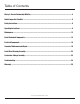
Table of Contents Wesley’s Service Partnership With You ................................................................................................. 4 Vehicle Inspection Checklist .................................................................................................................. 5 Safety Instructions................................................................................................................................ 6 Operating Instructions .....................................
Wesley’s Service Partnership With You Introduction Thank you for choosing a Wesley International electric utility vehicle. We are committed to delivering excellent service before, during and after the sale. By following the operating and maintenance instructions provided in this manual, we can work together to ensure you get the best from your Pack Mule® or Power MuleTM product.
Vehicle Inspection Checklist After Delivery Use the following checklist to inspect your vehicle upon delivery. Item Yes No 1. 2. 3. 4. 5. 6. Did you receive all accessories? Did you open and inspect all accessories? Are any accessories damaged? Are there dents or cracks on the vehicle? Are the tires in good condition and properly inflated to 60 psi? If you received an optional external battery charger, is the battery charger in good condition? 7.
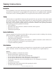
Safety Instructions Introduction The responsibility for safety lies with four main groups: manufacturers, owners, operators and maintenance personnel. As a manufacturer, our responsibility is to ensure that you are acquainted with the capabilities of the vehicle and to recommend guidelines for safe operation based on the vehicle’s characteristics. Training Vehicle owners are responsible for instructing their personnel in its safe operation.
Safety Instructions (cont’d) Safety Guidelines (continued) Driving (continued) • • • • • • • • • • • • • • • Exercise extreme caution when driving in reverse. Keep arms and legs within the operator’s platform while driving. Do not use the vehicle to push objects. Perform all recommended maintenance procedures at the specified intervals. Do not operate in sand, gravel or snow. Do not use the accelerator to hold the vehicle at a standstill on an incline.
Safety Instructions (cont’d) Fuses Follow these instructions when servicing the electrical system: • Never install a wire instead of the proper fuse, even for a temporary fix. It may cause extensive damage and possibly a fire. • Do not use a screwdriver or other metal object to remove fuses. Doing so may cause an electrical short circuit and damage the system. • Do not modify or tamper with any part of the operating or speed control systems.
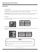
Operating Instructions Vehicle Controls Accelerator Pedal Seated Vehicles: The accelerator pedal is located to the right of the brake pedal. It controls the speed of the vehicle. It is operated with the right foot like the accelerator of an automobile. Standing Vehicles: One pedal functions as the accelerator and the brake. The speed is proportionate to the amount of pressure applied to the pedal. The vehicle brakes as pressure on the pedal is decreased.
Operating Instructions (cont’d) Charging Place the vehicle in a well-ventilated area and follow these steps to charge the battery: 1. Remove the deck for battery ventilation. 2. Check the battery’s water levels. 3. Plug the charger cord into the wall receptacle and into the charger receptacle located on the rear of the vehicle. 4. Turn the key switch to the CHARGE position. Driving Follow these steps to operate your Pack Mule or Power Mule vehicle: 1. Disconnect the battery charger.
Operating Instructions (cont’d) Loading Follow these guidelines when loading: • Do not exceed the specified number of passengers or load capacity for the vehicle. The maximum load capacity includes the combined weight of the passengers and cargo. • Make sure the cargo is balanced and securely loaded. Do not load cargo that can easily fall off of the vehicle. • Be very careful when handling cargo that is longer or wider than the vehicle. • Do not stack cargo so that the driver’s view is obstructed.
Maintenance Maintenance Schedule Safe, trouble-free operation of your electric utility vehicle depends on regular and proper preventive maintenance. The following chart is a guide for servicing all Pack Mule and Power Mule vehicles. WARNING Always disconnect the battery ground cable before servicing your vehicle. Failure to do so may result in serious injury or vehicle damage. Service Daily Check all gauges. Check horn. Check BDI for battery charge.
Maintenance (cont’d) Maintenance Schedule (continued) Service Daily Grease fork pivot fittings and gears with automotive grease using a grease gun. Inspect steering operations, gear housing and linkage. Wash batteries with baking soda and water. (Be sure charger is not plugged in). Dry batteries thoroughly before returning to service. Change oil level in transaxle. Clean, inspect, repack and reseal front axle and steering fork bearings. Lubricate steering chain and sprockets.
Basic Mechanical Components The following diagram shows the basic mechanical components in all Pack Mule and Power Mule vehicles. Although this is a drawing of the Stock Chaser SC 775, it generally applies to all vehicles.
Electrical Components The following table lists all of the parts in the electrical system.
Transaxle Maintenance and Repair Introduction Important considerations in assembling and disassembling the transaxle for the Pack Mules and Power Mules include cleanliness, replacement of bearings and seals, careful removal of snap rings, and the application of adequate torque on bolts, bearings and screws. For these procedures, the proper tools are required. Some of the service operations require special tools, e.g., oil seal, bearing and slide hammer pullers.
Transaxle Maintenance and Repair (cont’d) Torque Information Apply the following torque to the components listed below: Differential Bearing Caps ..................................................................................................... 35–45 Ft. Lbs. Ring Gear Bolts..................................................................................................................... 35–45 Ft. Lbs. Cover Plate Screws...................................................................................
Transaxle Maintenance and Repair (cont’d) Pack Mule Transaxle Assembly EUV Owner’s Manual 2 May 22, 2009 18
Transaxle Maintenance and Repair (cont’d) Pack Mule Transaxle Parts List # 3 4 5 6 7 8 9 10 11 12 13 15 16 17 18 19 23 23 24 24 25 25 25 26 28 29 30 31, 32, 33 34 Kit Part Gear, Input Ring, Retaining O-Ring Bearing, Ball Bearing, Ball Plug, End Cap Bearing, Ball Gear, Intermediate Assembly O-Ring Gear, Final Drive Bearing, Ball Screw, Cap Nut, Lock Plate, Cover Plug, Fill Screw, Cover Plate Brake Assembly, Left Hand Shoe Type Brake Assembly, Left Hand Shoe Type (Stock Chaser) Brake Assembly, Right Hand Sh
Transaxle Maintenance and Repair (cont’d) Power Mule Tugger Transaxle Assembly EUV Owner’s Manual 2 May 22, 2009 20
Transaxle Maintenance and Repair (cont’d) Power Mule Tugger Transaxle Parts List # 3 4 5 6 7 8 9 10 11 12 13 15 16 17 18 19 23 23 24 24 25 26 27 28 29 30 31 31 32 Kit 37 Part Gear, Input Retaining, Ring O-Ring Bearing, Ball Bearing, Ball Plug, End Cap Bearing, Ball Gear, Intermediate Assembly O-Ring Gear, Final Drive Bearing, Ball Screw, Cap Nut, Lock Plate, Cover Plug, Fill Screw, Cover Plate Brake Assembly, Left Hand Shoe Type Brake Assembly, Left Hand Shoe Type (Stock Chaser) Brake Assembly, Right Hand
Front Wheel Steering Assembly Front Wheel Assembly # Description Qty 1 EV-W016-PC 1 EV-W016-PMT 1 Dual Fork Assembly 1 Dual Fork Assembly, for PC series units (Not Shown) 1 Dual Fork Assembly, for PMT series units (Not Shown) 2 Dual Front Wheel Axle, 1˝ X 18˝ EV-W017 1 3 Sleeve EV-W007 2 3 Sleeve, for PMT series/Wide Tire units (Not Shown) EV-W007L 2 4 Spacer EV-W014 2 4 Spacer, for PMT series/Wide Tire units (Not Shown) EV-W011 2 5 1˝ Flat Washer EV-W027 6 6 1˝ Lock Was
Accelerator Linkage Assembly Accelerator Linkage (Standing Vehicles Only) # Description Part # Qty EV-E278 1 Chain EV-F216 1 Clevis Pin, 5/16˝ EV-D004 1 153 Cotter Pin, 1/8˝ EV-D016 1 157 Yoke End, 5/16˝ - 24 EV-D015 1 158 Spring EV-D006 3 159 Yoke End, 1/2˝ Right Hand Tread EV-D001 2 160 Brake Rod, 1/2˝ EV-D005 2 161 Yoke End, 1/2˝ Left Hand Tread EV-D003 2 162 Clevis Pin, 1/2˝ – 1 1/2˝ EV-D010 4 163 Lockwasher, 1/2˝ EV-D011 2 164 Cotter Pin EV-D012 4 165 H
Troubleshooting Introduction Be sure to follow all safety precautions when checking or repairing any part of the vehicle. Electrical adjustments control system adjustments should only be made by qualified personnel due to the use of special equipment and instruments. If you have questions about the sensitivity or difficulty of an adjustment, call Wesley International at 800-241-2869.
Troubleshooting (cont’d) Troubleshooting Tips (continued) Problem Rough or insufficient braking Possible Causes Worn brake shoes What to Do Replace and adjust brake shoes. Battery charger does not operate Blown fuse or tripped circuit breaker Inspect the circuit and replace the fuse or reset the circuit breaker. Faulty connections Check all battery and charger connections. Batteries fully charged Unplug the battery charger. Battery charger failure Replace the battery charger.
Troubleshooting (cont’d) Diagnosing Faults The controller includes a number of features designed to help the user track down operational, wiring, or internal controller faults. The diagnostic LED mounted next to the calibrator connectors on the front of the controller serves as a simple diagnostic tool. Use the table below to identify faults. Faults are cleared by re-initiating the start sequence.
Troubleshooting (cont’d) Calibrator Fault Identification Codes (cont’d) ID Code Fault Name Flash Fault 7 BELLY_SWITCH_PRESSED 2 8 SEAT_FAULT 2 9 IDLE_FAULT 2 10 MAINTENANCE_FAULT 9 11 FS1_RECYCLE_FAULT 2 12 SRO_FAULT 2 13 TWO_DIRECTION_FAULT 2 14 SEQUENCE_FAULT 2 15 LOW_BATTERY_FAULT 7 16 HIGH_BATTERY_FAULT 7 17 HIGH_CAP_VOLTAGE_FAULT 7 18 MOTOR_STALL_DETECTED 5 19 HIGH_BATTERY_WITHOUT_LINE_FAULT 7 20 CONFIGURATION_RANGE_FAULT 1 21 CONFIGURATION_CRC_FAULT 1 22
Warranty Warranty Policy PRODUCT REGISTRATION IS REQUIRED FOR WARRANTY COVERAGE. To register your product, complete and return the enclosed warranty card to Wesley International. Wesley International warrants to the original purchaser that their Pack Mule and Power Mule electric utility vehicles are free from defective factory material and workmanship. All warranties begin on the date of delivery to the first user. All warranty service must be approved by Wesley International prior to initiating repairs.
Warranty (cont’d) NOTICE OF LIABILITY All other warranties or conditions, expressed or implied, including merchantability, fitness for a particular purpose or otherwise, are limited in duration to the expressed warranty period and disclaimed in their entirety thereafter. Wesley International’s obligation under this warranty is strictly and exclusively limited to the replacement of defective parts. Wesley International does not assume or authorize anyone to assume any other obligation.
Notes EUV Owner’s Manual 2 May 22, 2009 30
Wesley International 3680 Chestnut Street Scottdale, Georgia 30079 Phone (404) 292-7441 • Toll Free (800) 241-2869 • Fax (404) 292-8469 www.WesleyInternational.