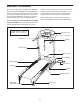
www.weslo.com Model No. WLTL29712.0 Serial No. Write the serial number in the space above for reference. Serial Number Decal QUESTIONS? If you have questions, or if parts are damaged or missing, DO NOT CONTACT THE STORE; please contact Customer Care. IMPORTANT: Please register this product (see the limited warranty on the back cover of this manual) before contacting Customer Care. CALL TOLL-FREE: 1-866-699-3756 Mon.–Fri. 6 a.m.–6 p.m. MT Sat. 8 a.m.–4 p.m. MT ON THE WEB: www.wesloservice.
TABLE OF CONTENTS WARNING DECAL PLACEMENT . . . . . . . . . . . . . . . . . . . . . . . . . . . . . . . . . . . . . . . . . . . . . . . . . . . . . . . . . . . . . . .2 IMPORTANT PRECAUTIONS. . . . . . . . . . . . . . . . . . . . . . . . . . . . . . . . . . . . . . . . . . . . . . . . . . . . . . . . . . . . . . . . . . 3 BEFORE YOU BEGIN. . . . . . . . . . . . . . . . . . . . . . . . . . . . . . . . . . . . . . . . . . . . . . . . . . . . . . . . . . . . . . . . . . . . . . . .5 ASSEMBLY . . . . . . . . .
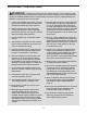
IMPORTANT PRECAUTIONS WARNING: To reduce the risk of burns, fire, electric shock, or injury to persons, read all important precautions and instructions in this manual and all warnings on your treadmill before using your treadmill. ICON assumes no responsibility for personal injury or property damage sustained by or through the use of this product. 1. It is the responsibility of the owner to ensure that all users of this treadmill are adequately informed of all warnings and precautions. 12.
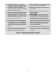
20. The heart rate monitor is not a medical device. Various factors, including the user’s movement, may affect the accuracy of heart rate readings. The heart rate monitor is intended only as an exercise aid in determining heart rate trends in general. 24. Do not change the incline of the treadmill by placing objects under the treadmill. 25. Never insert any object into any opening on the treadmill. 26. Inspect and properly tighten all parts of the treadmill regularly. 21.
BEFORE YOU BEGIN Thank you for selecting the new WESLO® CADENCE R 5.2 treadmill. The CADENCE R 5.2 treadmill offers a selection of features designed to make your workouts at home more effective. And when you’re not exercising, the unique treadmill can be folded up, requiring less than half the floor space of other treadmills. manual. To help us assist you, note the product model number and serial number before contacting us.
ASSEMBLY To hire an authorized service technician to assemble the treadmill, call 1-800-445-2480. Assembly requires two persons. Set the treadmill in a cleared area and remove all packing materials; do not dispose of the packing materials until assembly is completed. Note: After shipping, there may be an oily substance on the exterior of the treadmill. This is normal. If there is an oily substance on the treadmill, simply wipe it off with a soft cloth and a mild, non-abrasive cleaner.
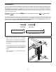
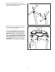
2. Attach the Handrails (69) to the Upright (73) with four M10 x 45mm Screws (2). Start all four Screws, and then tighten them. 2 2 69 2 73 3. With the help of a second person, hold the console assembly near the Upright (73). Remove the tie from the Upright Wire (71). 3 Console Assembly Connect the Upright Wire (71) to the console wire. See the inset drawing. The connectors should slide together easily and snap into place. If they do not, turn one connector and try again.
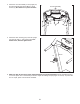
4. Attach the console assembly to the Upright (73) and the Handrails (69) with six M4.2 x 19mm Screws (3). Be careful not to pinch the wires. 4 Console Assembly 73 3 5. Attach the Latch Housing (72) to the left Upright (73) with two #10 x 1" Tek Screws (83); start both Screws, and then tighten them. 3 69 3 69 5 72 73 83 6. Make sure that all parts are properly tightened before you use the treadmill. Keep the included hex keys in a secure place.
OPERATION AND ADJUSTMENT HOW TO CONNECT THE POWER CORD nominal 120-volt circuit capable of carrying 15 or more amps. To avoid overloading the circuit, do not plug other electrical devices, except for lowpower devices such as cell phone chargers, into the surge suppressor or into an outlet on the same circuit. IMPORTANT: The treadmill is not compatible with GFCI-equipped outlets and may not be compatible with AFCI-equipped outlets.
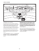
CONSOLE DIAGRAM Thumb Heart Rate Monitor Key Clip FEATURES OF THE CONSOLE IMPORTANT: If there is a sheet of plastic on the face of the console, remove the plastic. To prevent damage to the walking platform, wear clean athletic shoes while using the treadmill. The first time the treadmill is used, observe the alignment of the walking belt, and center the walking belt if necessary (see page 18). The treadmill console offers a selection of features designed to make your workouts more effective.
HOW TO TURN ON THE POWER HOW TO USE THE MANUAL MODE I MPORTANT: If the treadmill has been exposed to cold temperatures, allow it to warm to room temperature before turning on the power. If you do not do this, you may damage the console displays or other electrical components. 1. Insert the key into the console. lug in the power cord (see P page 9). Next, locate the power switch on the treadmill frame near the power cord. Make sure that the switch is in the reset position.
4. Follow your progress with the displays. 5. Measure your heart rate if desired. The track—The track represents a distance of 1/4 mile (400 m). As you walk or run on the treadmill, the indicators around the track will appear in succession until the entire track appears. The track will then disappear and the indicators will again begin to appear in succession. To measure your heart rate, stand on the foot rails and place your thumb on the heart rate monitor (see the drawing on page 10).
HOW TO USE A PRESET WORKOUT and the next segment of the profile will begin to flash. If a different speed setting is programmed for the next segment of the workout, the new speed setting will flash in the display to alert you. The treadmill will then automatically adjust to the speed setting for the next segment. 1. Insert the key into the console. See HOW TO TURN ON THE POWER on page 11. 2. Select a preset workout.
THE INFORMATION MODE HOW TO CHANGE THE INCLINE OF THE TREADMILL The console features an information mode that allows you to turn on and turn off the demo mode and to select miles or kilometers as the unit of measurement. The information mode also keeps track of treadmill usage information. To vary the intensity of your exercise, you can change the incline of the treadmill. There are two incline levels. Before changing the incline, remove the key and unplug the power cord.
HOW TO FOLD AND MOVE THE TREADMILL HOW TO FOLD THE TREADMILL HOW TO MOVE THE TREADMILL Before folding the treadmill, remove the key and unplug the power cord. CAUTION: You must be able to safely lift 45 lbs. (20 kg) to raise, lower, or move the treadmill. efore moving the treadmill, fold it as described at the B left. CAUTION: Make sure that the catch is resting against the latch pin. Moving the treadmill may require two people. 1.
TROUBLESHOOTING Most treadmill problems can be solved by following the simple steps below. Find the symptom that applies, and follow the steps listed. If further assistance is needed, see the front cover of this manual. d. If the treadmill still will not run, please see the front cover of this manual. SYMPTOM: The console displays remain lit when you remove the key from the console SYMPTOM: The power does not turn on a.
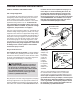
Remove the five indicated M4.2 x 19mm Washer Head Screws (9). Then, carefully remove the Motor Hood (56). b. If the walking belt is overtightened, treadmill performance may decrease and the walking belt may become damaged. Remove the key and UNPLUG THE POWER CORD. Using the hex key, turn both idler roller screws counterclockwise, 1/4 of a turn. When the walking belt is properly tightened, you should be able to lift each edge of the walking belt 2 to 3 in. (5 to 7 cm) off the walking platform.
SYMPTOM: The walking belt is off-center or slips when walked on b. I f the walking belt slips when walked on, first remove the key and UNPLUG THE POWER CORD. Using the hex key, turn both idler roller screws clockwise, 1/4 of a turn. When the walking belt is correctly tightened, you should be able to lift each edge of the walking belt 2 to 3 in. (5 to 7 cm) off the walking platform. Be careful to keep the walking belt centered.
EXERCISE GUIDELINES Burning Fat—To burn fat effectively, you must exercise at a low intensity level for a sustained period of time. During the first few minutes of exercise, your body uses carbohydrate calories for energy. Only after the first few minutes of exercise does your body begin to use stored fat calories for energy. If your goal is to burn fat, adjust the intensity of your exercise until your heart rate is near the lowest number in your training zone.
PART LIST Key No. Qty. 1 2 3 4 5 6 7 8 9 10 11 12 13 14 15 16 17 18 19 20 21 22 23 24 25 26 27 28 29 30 31 32 33 34 35 36 37 38 39 40 41 42 43 4 4 17 2 18 6 1 4 5 1 6 4 4 2 2 1 2 2 2 2 4 2 4 2 14 4 2 2 6 2 1 2 3 2 1 1 1 1 1 2 2 1 1 Model No. WLTL29712.0 R0712A Description Key No. Qty. M10 x 65mm Screw M10 x 45mm Screw M4.2 x 19mm Screw M8 x 35mm Screw M4.2 x 13mm Washer Head Screw M4.2 x 13mm Screw M4.2 x 13mm Tek Screw M4.2 x 19mm Tek Screw M4.2 x 19mm Washer Head Screw M4.
14 21 35 53 34 82 21 36 3 23 55 4 37 29 12 19 54 38 5 5 25 25 14 40 3 26 82 21 19 3 23 5 25 3 26 12 4 41 29 51 5 25 34 52 3 39 5 25 50 13 25 5 48 29 25 5 12 42 47 43 5 44 49 3 5 40 26 25 5 46 30 24 7 26 45 31 25 5 13 12 5 16 5 29 25 30 41 24 10 5 EXPLODED DRAWING A Model No. WLTL29712.
EXPLODED DRAWING B Model No. WLTL29712.
EXPLODED DRAWING C Model No. WLTL29712.
ORDERING REPLACEMENT PARTS To order replacement parts, please see the front cover of this manual.