Model No. WETL12706.0 Serial No. Serial Number Decal QUESTIONS? As a manufacturer, we are committed to providing complete customer satisfaction. If you have questions, or if there are missing or damaged parts, please call: 08457 089 009 or write: ICON Health & Fitness, Ltd. Customer Service Department Unit 4 Revie Road Industrial Estate Revie Road Beeston Leeds, LS118JG UK email: csuk@iconeurope.com CAUTION Read all precautions and instructions in this manual before using this equipment.
TABLE OF CONTENTS IMPORTANT PRECAUTIONS . . . . . . . . . . . . . . . . . . . . . . . . . . . . . . . . . . . . . . . . . . . . . . . . . . . . . . . . . . . . . . . . .3 BEFORE YOU BEGIN . . . . . . . . . . . . . . . . . . . . . . . . . . . . . . . . . . . . . . . . . . . . . . . . . . . . . . . . . . . . . . . . . . . . . . .5 ASSEMBLY . . . . . . . . . . . . . . . . . . . . . . . . . . . . . . . . . . . . . . . . . . . . . . . . . . . . . . . . . . . . . . . . . . . . . . . . . . . . . . .
IMPORTANT PRECAUTIONS WARNING: To reduce the risk of burns, fire, electric shock, or injury to persons, read the following important precautions and information before operating the treadmill. 1. It is the responsibility of the owner to ensure that all users of this treadmill are adequately informed of all warnings and precautions. 11. If an extension cord is needed, use only a 3conductor, 1mm2 (14-gauge) cord that is no longer than 1.5 m (5 ft.). 2. Use the treadmill only as described in this manual.
21. Do not change the incline of the treadmill by placing objects under the treadmill. tenance and adjustment procedures described in this manual. Never remove the motor hood unless instructed to do so by an authorized service representative. Servicing other than the procedures in this manual should be performed by an authorized service representative only. 22. Inspect and properly tighten all parts of the treadmill regularly. 23. Never drop or insert any object into any opening. 24. 25.
BEFORE YOU BEGIN Thank you for selecting the new WESLO® CADENCE M5 treadmill. The CADENCE M5 treadmill combines advanced technology with innovative design to make your workouts at home more effective and enjoyable. And when you’re not exercising, the CADENCE M5 treadmill can be folded up, requiring less than half the floor space of other treadmills. ing this manual, please see the front cover of this manual. To help us assist you, please note the product model number and serial number before contacting us.
ASSEMBLY Assembly requires two persons. Set the treadmill in a cleared area and remove all packing materials; do not dispose of the packing materials until assembly is completed. Note: The underside of the treadmill walking belt is coated with high-performance lubricant. During shipping, a small amount of lubricant may be transferred to the top of the walking belt or the shipping carton. This does not affect treadmill performance.
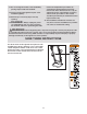
3. Have a second person lift and hold the front end of the Frame (51). Hold a Frame Spacer (11) between the Right Handrail (54) and the Frame. Attach the Right Handrail to the Frame with a Frame Pivot Bolt (1), a Frame Washer (14), and a Handrail Star Washer (9). Do not tighten the Frame Pivot Bolts yet. 3 54 11 Repeat this step on the left side of the treadmill. 14 1 9 51 4. Hold the Console Assembly (91) near the Right Handrail (54). Touch the Right Handrail to discharge any static.
6. Attach the Console Back (93) to the Console Assembly (91) with four Console Back Screws (4). Note that there is a slot in the side of the Console Back for the Wire Harness (98). Make sure that no wires are pinched. 6 93 91 4 98 7. Carefully lower the Handrails (53, 54) until they are touching the floor. 4 7 2 1 See the lower drawing. Position the Handrails (53, 54) so that the treadmill Frame (51) is centered between the Handrails.
8. Attach the Latch Assembly (48) to the Left Handrail (53) with two Latch Screws (7). Make sure that the Latch Assembly is oriented as shown. 8 7 See HOW TO CHANGE THE INCLINE OF THE TREADMILL on page 14, and insert the two Incline Pins into the Incline Legs. 53 48 9. Make sure that all parts are properly tightened before you use the treadmill. Keep the included hex key in a secure place. The hex key is used to adjust the walking belt (see page 18).
OPERATION AND ADJUSTMENT THE PRE-LUBRICATED WALKING BELT Your treadmill features a walking belt coated with high-performance lubricant. IMPORTANT: Never apply silicone spray or other substances to the walking belt or the walking platform. Such substances will deteriorate the walking belt and cause excessive wear. HOW TO PLUG IN THE POWER CORD This product must be earthed.
CONSOLE DIAGRAM Key Note: If there are thin sheets of plastic on the console, remove the plastic. Clip FEATURES OF THE CONSOLE HOW TO TURN ON THE POWER The treadmill console offers a selection of features designed to make your workouts more effective. Plug in the power cord (see page 10). Next, locate the on/off switch on the treadmill frame near the right upright. Make sure that the switch is in the “on” position.
The lower right display—The lower right display can show the speed of the walking belt and the approximate number of calories that you have burned. The display also shows your heart rate when you use the handgrip pulse sensor (see step 5). HOW TO USE THE MANUAL MODE 1 Insert the key into the console. See HOW TO TURN ON THE POWER on page 11. 2 Select the manual mode.
5 Each program consists of 30 one-minute periods. One speed setting is programmed for each period. Note: The same speed setting may be programmed for two or more consecutive periods. The profiles on the console show how the speed of the walking belt will change during the programs. Measure your heart rate if desired. Before using the handgrip pulse sensor, remove the sheets of clear plastic from the metal contacts. In addition, make sure that your hands are clean.
HOW TO CHANGE THE INCLINE OF THE TREADMILL To vary the intensity of your exercise, you can change the incline of the treadmill. There are three incline levels. Before changing the incline, remove the key and unplug the power cord. Next, fold the treadmill to the storage position (see page 15). To change the incline, first remove the incline pin from one of the incline legs. Adjust the incline leg to the desired position, and then fully reinsert the incline pin.
HOW TO FOLD AND MOVE THE TREADMILL HOW TO FOLD THE TREADMILL FOR STORAGE 1 Unplug the power cord. CAUTION: You must be able to safely lift 20 kg (45 lbs.) to raise, lower, or move the treadmill. 1. Hold the metal frame firmly in the location shown by the arrow at the right. CAUTION: To decrease the possibility of injury, do not lift the frame by the plastic foot rails. Make sure to bend your legs and keep your back straight. As you raise the frame, make sure to lift with your legs rather than your back.
HOW TO LOWER THE TREADMILL FOR USE 1. Hold the upper end of the treadmill with your right hand as shown. Using your left hand, pull the latch knob to the left and hold it. Next, lower the frame until it is past the latch pin. Then, release the latch knob. Latch Pin Latch Knob Catch 2. Hold the frame firmly with both hands, and lower it to the floor. To decrease the possibility of injury, bend your legs and keep your back straight.
MAINTENANCE AND TROUBLESHOOTING Most treadmill problems can be solved by following the steps below. Find the symptom that applies, and follow the steps listed. If further assistance is needed, please see the front cover of this manual. PROBLEM: The power does not turn on SOLUTION: a. Make sure that the power cord is plugged into a properly earthed outlet (see page 10). If an extension cord is needed, use only a 3-conductor, 1 mm2 (14-gauge) cord that is no longer than 1.5 m (5 ft.).
Locate the Reed Switch (97) and the Magnet (62) on the left side of the Pulley (71). Turn the Pulley until the Magnet is aligned with the Reed Switch. Make sure that the gap between the Magnet and the Reed Switch is about 3 mm (1/8 in.). If necessary, loosen the Screw (21), move the Reed Switch slightly, and then retighten the Screw. Reattach the Hood (not shown), and run the treadmill for a few minutes to check for a correct speed reading.
CONDITIONING GUIDELINES is to burn fat, adjust the speed and incline of the treadmill until your heart rate is near the lowest number in your training zone. WARNING: Before beginning this or any exercise program, consult your physician. This is especially important for individuals over the age of 35 or individuals with preexisting health problems. For maximum fat burning, adjust the speed and incline of the treadmill until your heart rate is near the middle number in your training zone.
PART LIST—Model No. WETL12706.0 Key No. Qty.
4 Bolt (120)–2 PART IDENTIFICATION CHART Remove this chart and use it to identify small parts during assembly. Save this chart and the EXPLODED DRAWING/PART LIST for future reference.
19 29 32 43 46 13 69 74 60 36 21 42 25 17 27 43 6 67 18 29 46 25 36 74 21 42 55 78 27 46 43 46 61 25 50 69 41 64 25 19 94 43 25 28 13 32 41 25 86 68 33 77 76 25 51 62 83 97 81 71 45 56 25 20 41 41 50 21 28 22 58 41 20 77 21 87 34 23 40 88 44 38 45 94 31 96 49 59 38 37 33 30 34 79 78 21 46 72 73 41 49 66 95 21 42 20 20 39 47 57 24 21 85 89 21 21 84 41 99 10 20 39 21 42 24 15 47 4 4 47 90 47 53 4
ORDERING REPLACEMENT PARTS To order replacement parts, contact the ICON Health & Fitness, Ltd. office, or write: ICON Health & Fitness, Ltd. Customer Service Department Unit 4, Revie Road Industrial Estate Revie Road Beeston Leeds, LS118JG UK Tel: 08457 089 009 Outside the UK: (44) 0113 387 7133 Fax: (44) 0113 387 7125 To help us assist you, please be prepared to provide the following information: • the MODEL NUMBER of the product (WETL12706.