www.weslo.com Model No. WLEX31510.0 Serial No. Write the serial number in the space above for reference. Serial Number Decal QUESTIONS? If you have questions, or if parts are damaged or missing, DO NOT CONTACT THE STORE; please contact Customer Care. IMPORTANT: Please register this product (see the limited warranty on the back cover of this manual) before contacting Customer Care. 1-866-699-3756 CALL TOLL-FREE: Mon.–Fri., 6 a.m.–6 p.m. MT Sat. 8 a.m.–4 p.m. MT ON THE WEB: www.wesloservice.
TABLE OF CONTENTS WARNING DECAL PLACEMENT . . . . . . . . . . . . . . . . . . . . . . . . . . . . . . . . . . . . . . . . . . . . . . . . . . . . . . . . . . . . . .2 IMPORTANT PRECAUTIONS . . . . . . . . . . . . . . . . . . . . . . . . . . . . . . . . . . . . . . . . . . . . . . . . . . . . . . . . . . . . . . . .3 BEFORE YOU BEGIN . . . . . . . . . . . . . . . . . . . . . . . . . . . . . . . . . . . . . . . . . . . . . . . . . . . . . . . . . . . . . . . . . . . . . .4 ASSEMBLY . . . . . . . . . . . . .
IMPORTANT PRECAUTIONS WARNING: To reduce the risk of serious injury, read all important precautions and instructions in this manual and all warnings on your exercise bike before using your exercise bike. ICON assumes no responsibility for personal injury or property damage sustained by or through the use of this product. 8. Wear appropriate clothes while exercising; do not wear loose clothes that could become caught on the exercise bike. Always wear athletic shoes for foot protection. 1.
BEFORE YOU BEGIN Thank you for selecting the new WESLO® PURSUIT CT 2.0 R exercise bike. Cycling is an effective exercise for increasing cardiovascular fitness, building endurance, and toning the body. The PURSUIT CT 2.0 R exercise bike provides a selection of features designed to make your workouts at home more effective and enjoyable. after reading this manual, please see the front cover of this manual. To help us assist you, note the product model number and serial number before contacting us.
ASSEMBLY To hire an authorized service technician to assemble the exercise bike, call 1-800-445-2480. Assembly requires two persons. Place all parts of the exercise bike in a cleared area and remove the packing materials. Do not dispose of the packing materials until assembly is completed. In addition to the included tool(s), assembly requires a Phillips screwdriver wrench , and pliers . , an adjustable See the drawings below to identify the small parts needed for assembly.
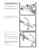
1. 1 To make assembly easier, read the information on page 5 before you begin. 2 33 Orient the Front Stabilizer (2) so that the large holes are facing the Frame (1). Attach the Front Stabilizer (2) to the Frame (1) with two M10 x 65mm Button Screws (33). Large Holes 2. Attach the Rear Stabilizer (6) to the Seat Frame (5) with two M10 x 70mm Carriage Bolts (30) and two M10 Locknuts (65). 1 2 65 5 65 6 30 3. Insert the end of the Seat Frame (5) into the Frame (1).
4. Attach the Left and Right Seat Brackets (14, 15) to the Seat Frame (5) with two M8 x 125mm Bolts (62), four M8 Washers (54), and two M8 Locknuts (10) as shown. Do not fully tighten the Locknuts yet. 4 54 10 54 10 54 54 62 5. Attach a Seat Handle (59) to the round tube on the Left Seat Bracket (14) with two M6 x 30mm Button Bolts (64), two M6 Curved Washers (69), and two M6 Locknuts (63). 14 5 5 59 Attach the other Seat Handle (59) to the Right Seat Bracket (15) in the same way. 63 59 6.
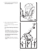
7. Attach the Seat (12) to the Seat Brackets (14, 15) with four M6 x 35mm Button Screws (61) and four M6 Washers (68). 7 12 15 14 68 68 68 61 61 8. Have a second person hold the Upright (13) near the Frame (1) until step 9. 8 Connect the Extension Wire (52) to the Reed Wire (43). Then, connect the Resistance Cable (19) to the Lower Resistance Cable (45) in the following way: • See drawing A.
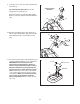
. Insert the excess wire and cable downward into the Frame (1). 9 Tip: Avoid pinching the wires. Insert the Upright (13) into the Frame (1). Attach the Upright (13) with three M8 x 20mm Button Screws (34) and three M8 Split Washers (42). Avoid pinching the wires 34 10. Attach the Handlebar (53) to the Upright (13) with two M8 x 65mm Button Bolts (36), two M8 Curved Washers (46), and two M8 Locknuts (10). 10 42 13 10 46 13 42 1 34 53 36 11.
12. While a second person holds the Console (16) near the Upright (13), connect the wire on the Console to the Extension Wire (52). 12 Insert the wires downward into the Upright (13). Tip: Avoid pinching the wires. Attach the Console (16) to the Upright (13) with four M4 x 15mm Self-tapping Screws (47). 13. Identify the Left Pedal (24), which is marked with an “L.” Using an adjustable wrench, firmly tighten the Left Pedal (24) counterclockwise into the left arm of the Crank (21).
HOW TO USE THE EXERCISE BIKE HOW TO ADJUST THE SEAT FRAME HOW TO ADJUST THE PEDALING RESISTANCE For effective exercise, the seat should be in the proper position. As you pedal, there should be a slight bend in your knees when the pedals are in the most forward position. Seat Frame To increase the resistance of the pedals, turn the resistance knob clockwise; to decrease the resistance, turn the knob counterclockwise. IMPORTANT: Stop turning the knob when turning becomes difficult, or damage may result.
FEATURES OF THE CONSOLE HOW TO USE THE MANUAL MODE 1. Turn on the console. To turn on the console, press any of the buttons or begin pedaling. The entire display and the pace guide will turn on for a moment; the console will then be ready for use. 2. Select the manual mode. When you turn on the console, the manual mode will be selected. If you have selected a pace workout, reselect the manual mode by pressing the Workout Select button repeatedly until zeros appear in the display. 3.
When you turn Indicators on the console, the scan mode will be selected automatically. One indicator will appear below the word Scan to show that the scan mode is selected, and a second indicator will show which information is currently displayed. Note: When the batteries are replaced, it may be necessary to reselect the desired unit of measurement. To reset the display, press the On/Reset button. To pause the console, stop pedaling. The time will flash if it is displayed.
HOW TO USE A PACE WORKOUT During the workout, the pace guide will prompt you to keep your pedaling speed near the target pace for the current segment. When the left indicator lights, increase your speed; when the right indicator lights, decrease your speed. When the center indicator lights, maintain your current speed. IMPORTANT: The pace guide is intended only to provide a goal. Make sure to pedal at a speed that is comfortable for you. 1. Turn on the console. See step 1 on page 12. 2.
MAINTENANCE AND TROUBLESHOOTING Inspect and tighten all parts of the exercise bike regularly. Replace any worn parts immediately. Turn the Resistance Knob (27) to the lowest setting. Then, locate the Reed Switch (43). Turn the Pulley (21) until the Magnet (38) is aligned with the Reed Switch. Loosen, but do not remove, the M4 x 15mm Self-tapping Screw (47). To clean the exercise bike, use a damp cloth and a small amount of mild detergent.
HOW TO ADJUST THE DRIVE BELT If you can feel the pedals slip while you are pedaling, even when the resistance is at the highest level, the drive belt may need to be adjusted. To adjust the drive belt, you must first remove the right pedal and the right shield as described below. Using an adjustable wrench, turn the right pedal counterclockwise and remove it.
EXERCISE GUIDELINES WARNING: Burning Fat—To burn fat effectively, you must exercise at a low intensity level for a sustained period of time. During the first few minutes of exercise, your body uses carbohydrate calories for energy. Only after the first few minutes of exercise does your body begin to use stored fat calories for energy. If your goal is to burn fat, adjust the intensity of your exercise until your heart rate is near the lowest number in your training zone.
PART LIST—Model No. WLEX31510.0 Key No. Qty. 1 2 3 4 5 6 7 8 9 10 11 12 13 14 15 16 17 18 19 20 21 22 23 24 25 26 27 28 29 30 31 32 33 34 35 36 37 1 1 2 2 1 1 2 2 1 7 1 1 1 1 1 1 1 1 1 1 1 1 1 1 2 1 1 2 2 2 2 1 2 3 1 2 1 Description Key No. Qty.
EXPLODED DRAWING—Model No. WLEX31510.
ORDERING REPLACEMENT PARTS To order replacement parts, please see the front cover of this manual.