weslo.com Model No. WLEL32115.1 Serial No. Write the serial number in the space above for reference. Serial Number Decal ACTIVATE YOUR WARRANTY To register your product and activate your warranty today, go to my.weslo.com. CUSTOMER CARE For service at any time, go to wesloservice.com. Or call 1-866-699-3756 Mon.–Fri. 6 a.m.–6 p.m. MT Sat. 8 a.m.–12 p.m. MT Please do not contact the store. CAUTION Read all precautions and instructions in this manual before using this equipment.
TABLE OF CONTENTS WARNING DECAL PLACEMENT . . . . . . . . . . . . . . . . . . . . . . . . . . . . . . . . . . . . . . . . . . . . . . . . . . . . . . . . . . . . . . .2 IMPORTANT PRECAUTIONS. . . . . . . . . . . . . . . . . . . . . . . . . . . . . . . . . . . . . . . . . . . . . . . . . . . . . . . . . . . . . . . . . . 3 BEFORE YOU BEGIN. . . . . . . . . . . . . . . . . . . . . . . . . . . . . . . . . . . . . . . . . . . . . . . . . . . . . . . . . . . . . . . . . . . . . . . .5 PART IDENTIFICATION CHART.
IMPORTANT PRECAUTIONS WARNING: To reduce the risk of serious injury, read all important precautions and instructions in this manual and all warnings on your hybrid trainer before using your hybrid trainer. ICON assumes no responsibility for personal injury or property damage sustained by or through the use of this product. 1. It is the responsibility of the owner to ensure that all users of the hybrid trainer are adequately informed of all precautions. 9.
STANDARD SERVICE PLANS all 4
BEFORE YOU BEGIN Thank you for selecting the revolutionary WESLO® MOMENTUM G 3.2 hybrid trainer. The MOMENTUM G 3.2 hybrid trainer provides an impressive selection of features designed to make your workouts at home more effective and enjoyable. reading this manual, please see the front cover of this manual. To help us assist you, note the product model number and serial number before contacting us. The model number and the location of the serial number decal are shown on the front cover of this manual.
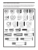
PART IDENTIFICATION CHART Use the drawings below to identify the small parts needed for assembly. The number in parentheses below each drawing is the key number of the part, from the PART LIST near the end of this manual. The number following the key number is the quantity needed for assembly. Note: If a part is not in the hardware kit, check to see if it has been preassembled. Extra parts may be included.
ASSEMBLY • To hire an authorized service technician to assemble the hybrid trainer, call 1-800-445-2480. • In addition to the included tool(s), assembly requires the following tools: • Assembly requires two persons. one Phillips screwdriver • Place all parts in a cleared area and remove the packing materials. Do not dispose of the packing materials until you finish assembly. one adjustable wrench • Left parts are marked “L” or “Left” and right parts are marked “R” or “Right.
3. While a second person lifts the front of the Frame (1), attach the Front Stabilizer (10) to the Frame with two M8 x 65mm Carriage Bolts (51), two M8 Curved Washers (101), two M8 Split Washers (63), and two M8 Acorn Nuts (58); insert both Carriage Bolts, and then tighten the Acorn Nuts. 3 58 63 101 1 10 51 58 63 101 4. While a second person holds the Upright (2) near the Frame (1), connect the Upright Wire (31) to the Reed Switch Wire (47).
5. Tip: Avoid pinching the wires and cables during this step. 5 Slide the Upright (2) onto the Frame (1). Attach the Upright (2) with three M8 x 20mm Screws (54), three M8 Split Washers (63), and three M8 Washers (55). Do not tighten the Screws yet. Avoid pinching the wires and cables See the inset drawing. Attach the Upright (2) with two M8 x 60mm Bolts (90), four M8 Washers (55), and two M8 Locknuts (53). Do not tighten the Locknuts yet.
6. Have a second person hold the Handlebar (52) near the Upright (2). 6 See the inset drawing. Insert the Pulse Wires (A) through the Grommet (99), into the left side of the Upright (2), and out of the top of the Upright. Then, press the Grommet into the left side of the Upright. 86 88 63 55 52 A 2 Tip: Avoid pinching the Pulse Wires (A).
8. Finger tighten an M8 x 20mm Hex Screw (57) with an M8 Split Washer (63), an M8 Large Washer (72), and an M8 Plastic Washer (27) into one end of the Upright Axle (26). 8 57 Using a plastic bag to keep your hands clean, apply a generous amount of the included grease to the Upright Axle (26) and to two Wave Washers (73). 63 72 27 26 Next, orient the Left Upper Body Arm (5) assembly as shown. Make sure that the wide side (C) of the tube is in the indicated location.
10. Finger tighten an M8 x 20mm Hex Screw (57) with an M8 Split Washer (63), an M8 Large Washer (72), and an M8 Plastic Washer (27) into the right end of the Upright Axle (26). 10 Then, tighten both M8 x 20mm Hex Screws (57) at the same time. 83 Next, identify the two 8mm Dome Caps (83), the four 17mm Dome Caps (not shown), and the two 19mm Dome Caps (not shown). 57 72 27 Press an 8mm Dome Cap (83) firmly onto each M8 Large Washer (72). 72 63 57 26 11.
12. Apply grease to an M10 x 70mm Bolt (60). 12 Attach the right Pedal Arm (11) to the right Upper Body Leg (64) with the M10 x 70mm Bolt (60), two M10 Washers (92), two M10 Plastic Washers (62), and an M10 Locknut (93) as shown. Make sure to place the Plastic Washers between the right Upper Body Leg and the right Pedal Arm. 64 Then, press a 17mm Dome Cap (14) firmly onto each M10 Washer (92). Attach the left Pedal Arm (11) to the left Upper Body Leg (64) in the same way.
. The Console (23) can use two AA batteries (not included); alkaline batteries are recommended. Do not use old and new batteries together or alkaline, standard, and rechargeable batteries together. IMPORTANT: If the Console has been exposed to cold temperatures, allow it to warm to room temperature before inserting batteries. Otherwise, you may damage the Console or other electronic components.
17. Insert the Seat Post (24) into the Frame (1). 17 Adjust the Seat Post (24) to the desired height, and insert the Seat Post Knob (87) into the indicated hole (E) in the Frame (1) and into one of the adjustment holes (F) in the Seat Post. Tighten the Seat Post Knob (87). Make sure that the Seat Post Knob is inserted into one of the adjustment holes (F) in the Seat Post (24). F 24 E 1 18. Attach the Water Bottle Holder (81) to the Upright (2) with two M4 x 12mm Screws (66). 87 18 81 66 2 19.
HOW TO USE THE HYBRID TRAINER HOW TO MOVE THE HYBRID TRAINER HOW TO USE THE ELLIPTICAL MODE Due to the size and weight of the hybrid trainer, moving it requires two persons. Stand in front of the hybrid trainer, hold the upright (A), and place one foot against one of the front stabilizer caps (B). Pull on the upright and have a second person lift the rear stabilizer (C) until the hybrid trainer will roll on the front stabilizer caps.
HOW TO USE THE UPRIGHT BIKE MODE To adjust the height of the seat, first loosen and remove the seat post knob (H). Next, slide the seat post upward or downward and align one of the adjustment holes in the seat post with the hole in the frame. Insert the seat post knob into the frame and the seat post, and then tighten the seat post knob. Make sure that the seat post knob is inserted into one of the adjustment holes in the seat post.
CONSOLE DIAGRAM FEATURES OF THE CONSOLE The easy-to-use console features six modes that provide instant exercise feedback during your workouts. Scan (SCAN)—This mode displays the time, speed, distance, calories, and pulse modes, for a few seconds each, in a repeating cycle. Time (TMR)—This mode displays the elapsed time. Note: If you set a time goal (see step 2 on page 19), this display will show the time remaining in your workout. Speed (SPD)—This mode displays your pedaling speed, in miles per hour.
HOW TO USE THE CONSOLE To reset the display and all the modes to zero, press and hold the Reset button for several seconds. Make sure that batteries (not included) are installed in the console (see assembly step 14 on page 14). If there is a sheet of plastic on the console, remove the plastic. 4. Measure your heart rate if desired. ote: If there N are sheets A of plastic on the metal contacts (A) of the handgrip heart rate monitor, remove the plastic.
FCC INFORMATION This equipment has been tested and found to comply with the limits for a Class B digital device, pursuant to part 15 of the FCC Rules. These limits are designed to provide reasonable protection against harmful interference in a residential installation. This equipment generates, uses, and can radiate radio frequency energy and, if not installed and used in accordance with the instructions, may cause harmful interference to radio communications.
MAINTENANCE AND TROUBLESHOOTING MAINTENANCE Next, carefully pull the Right Shield (4) outward and upward until you can reach the Idler Adjustment Bolt (34). Regular maintenance is important for optimal performance and to reduce wear. Inspect and properly tighten all parts each time the hybrid trainer is used. Replace any worn parts immediately. To clean the hybrid trainer, use a damp cloth and a small amount of mild soap.
EXERCISE GUIDELINES Burning Fat—To burn fat effectively, you must exercise at a low intensity level for a sustained period of time. During the first few minutes of exercise, your body uses carbohydrate calories for energy. Only after the first few minutes of exercise does your body begin to use stored fat calories for energy. If your goal is to burn fat, adjust the intensity of your exercise until your heart rate is near the lowest number in your training zone.
SUGGESTED STRETCHES The correct form for several basic stretches is shown at the right. Move slowly as you stretch; never bounce. 1. Toe Touch Stretch Stand with your knees bent slightly and slowly bend forward from your hips. Allow your back and shoulders to relax as you reach down toward your toes as far as possible. Hold for 15 counts, then relax. Repeat 3 times. Stretches: Hamstrings, back of knees and back. 1 2. Hamstring Stretch Sit with one leg extended.
PART LIST Key No. Qty. 1 2 3 4 5 6 7 8 9 10 11 12 13 14 15 16 17 18 19 20 21 22 23 24 25 26 27 28 29 30 31 32 33 34 35 36 37 38 39 40 41 42 43 44 45 1 1 1 1 1 1 1 2 1 1 2 1 1 4 1 1 1 1 1 1 2 1 1 1 1 1 4 1 3 2 1 1 2 1 1 1 1 1 2 6 4 1 3 2 1 Model No. WLEL32115.1 R0318A Description Key No. Qty.
Key No. Qty. 91 92 93 94 95 96 97 4 8 6 2 1 2 2 Description Key No. Qty. M10 x 45mm Bolt M10 Washer M10 Locknut Small Curved Washer Short Flywheel Spacer Crank Cover Seat Carriage Cap 98 99 100 101 102 * * 1 1 2 2 2 – – Description M8 x 40mm Socket Bolt Grommet M8 x 65mm Bolt M8 Curved Washer Nylon Spacer Userʼs Manual Assembly Tool Note: Specifications are subject to change without notice. For information about ordering replacement parts, see the back cover of this manual.
68 68 102 15 41 59 42 44 11 3 41 68 27 13 53 68 55 93 9 77 93 68 4 39 82 96 92 91 48 55 92 47 28 22 49 78 43 98 39 82 60 20 79 100 33 68 35 30 14 30 92 53 24 93 87 55 43 14 1 33 20 18 45 54 84 55 53 55 21 59 97 74 37 12 84 32 38 27 41 49 58 63 101 43 36 74 34 63 101 53 44 58 53 17 50 29 41 70 7 46 97 61 69 92 96 10 29 102 93 95 16 19 51 93 14 46 92 11 60 93 91 14 21 92 EXPLODED DRAWING A Model No
83 57 63 72 56 27 62 40 27 89 65 8 67 5 58 62 63 65 64 55 40 40 86 73 63 26 55 71 90 54 90 88 80 63 54 66 52 94 71 99 80 63 31 55 55 25 81 68 85 53 55 66 73 75 62 40 56 76 54 40 63 53 2 23 89 65 6 8 27 63 72 62 55 65 64 40 67 58 63 57 83 EXPLODED DRAWING B Model No. WLEL32115.
ORDERING REPLACEMENT PARTS To order replacement parts, please see the front cover of this manual.