www.weslo.com Model No. WLEL83012.0 Serial No. Write the serial number in the space above for reference. Serial Number Decal (under frame) QUESTIONS? If you have questions, or if parts are damaged or missing, DO NOT CONTACT THE STORE; please contact Customer Care. IMPORTANT: Please register this product (see the limited warranty on the back cover of this manual) before contacting Customer Care. CALL TOLL-FREE: 1-866-699-3756 Mon.–Fri., 6 a.m.–6 p.m. MT Sat. 8 a.m.–4 p.m. MT ON THE WEB: www.wesloservice.
TABLE OF CONTENTS WARNING DECAL PLACEMENT . . . . . . . . . . . . . . . . . . . . . . . . . . . . . . . . . . . . . . . . . . . . . . . . . . . . . . . . . . . . . . .2 IMPORTANT PRECAUTIONS. . . . . . . . . . . . . . . . . . . . . . . . . . . . . . . . . . . . . . . . . . . . . . . . . . . . . . . . . . . . . . . . . . 3 BEFORE YOU BEGIN. . . . . . . . . . . . . . . . . . . . . . . . . . . . . . . . . . . . . . . . . . . . . . . . . . . . . . . . . . . . . . . . . . . . . . . .4 PART IDENTIFICATION CHART.
IMPORTANT PRECAUTIONS WARNING: To reduce the risk of serious injury, read all important precautions and instructions in this manual and all warnings on your elliptical before using your elliptical. ICON assumes no responsibility for personal injury or property damage sustained by or through the use of this product. 1. It is the responsibility of the owner to ensure that all users of the elliptical are adequately informed of all precautions. 9.
BEFORE YOU BEGIN Thank you for selecting the new WESLO® MOMENTUM R 5.2 elliptical. The MOMENTUM R 5.2 elliptical provides a selection of features designed to make your workouts at home more effective and enjoyable. reading this manual, please see the front cover of this manual. To help us assist you, note the product model number and serial number before contacting us. The model number and the location of the serial number decal are shown on the front cover of this manual.
PART IDENTIFICATION CHART Use the drawings below to identify the small parts needed for assembly. The number in parentheses below each drawing is the key number of the part, from the PART LIST near the end of this manual. The number following the key number is the quantity needed for assembly. Note: If a part is not in the hardware kit, check to see if it has been preassembled.
ASSEMBLY • To hire an authorized service technician to assemble this product, call 1-800-445-2480. • In addition to the included tool(s), assembly requires the following tools: • Assembly requires two persons. one adjustable wrench • Place all parts in a cleared area and remove the packing materials. Do not dispose of the packing materials until you finish all assembly steps. one Phillips screwdriver • Left parts are marked “L” or “Left” and right parts are marked “R” or “Right.
2. If there is a cardboard tube (not shown) on the front the Frame (54), remove and discard the attachment screw and the cardboard tube. 2 37 Set a sturdy piece of packing material under the front of the Frame (54). Have a second person hold the Frame to prevent it from tipping while you complete this step. 71 8 Attach the Front Stabilizer (37) to the Frame (54) with two M8 x 82mm Screws (53), two M8 Split Washers (8), and two M8 Washers (71). 54 Remove the packing material. 3.
4. Attach the Right Pedal Arm Cover (85) to the Right Pedal Arm (75) with an M4 x 20mm Selftapping Screw (45). 4 Repeat this step on the other side of the elliptical. 85 75 45 5. Orient the Upright (9) assembly and the Lower Upright Cover (83) as shown. Slide the Lower Upright Cover upward onto the Upright. 5 Have a second person hold the Upright (9) and the Lower Upright Cover (83) near the Frame (54). Connect the Extension Wire (16) to the Main Wire (26).
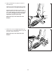
6. Apply a small amount of grease to an M10 x 76mm Bolt (30). 6 Hold the end of the Right Upper Body Leg (80) inside the bracket on the Right Pedal Arm (75). Attach the Right Upper Body Leg (80) to the Right Pedal Arm (75) with the M10 x 76mm Bolt (30), an M10 Washer (10), and an M10 Locknut (32). Do not overtighten the Bolt; the Right Upper Body Leg must pivot freely. 80 32 10 Grease Repeat this step on the other side of the elliptical. 30 75 7.
8. Orient the Handlebar (4) as shown. 8 Have a second person hold the Handlebar (4) near the Upright (9). Insert the Extension Wire (16) into the Handlebar and pull it out of the top of the Handlebar. 4 16 7 Tip: Avoid pinching the wires. Attach the Handlebar (4) to the Upright (9) with three M8 x 20mm Screws (7). 7 9 9. Slide the Right Upper Body Arm (15) onto the Right Upper Body Leg (80).
10. Attach a set of Upper Body Covers A and B (88, 89) to the Right Upper Body Arm (15) and the Right Upper Body Leg (80) with two M3 x 20mm Screws (79). 10 Repeat this step on the other side of the elliptical. 15 See assembly step 6. Tighten the M8 x 78mm Bolts (38) and the M8 x 16mm Screws (35). Then, press the Lower Upright Cover (83) into place. 88 89 80 79 83 35 11. The Console (1) can use four AA batteries (not included); alkaline batteries are recommended.
. While a second person holds the Console (1) near the Handlebar (4), connect the console wires to the Extension Wire (16) and to the Pulse Wires (6). 12 Avoid pinching the wires 1 Insert the excess wire into the Console (1) or into the Handlebar (4). 6 Tip: Avoid pinching the wires. Attach the Console (1) to the Handlebar (4) with four M4 x 16mm Screws (2). 4 16 2 13. Make sure that all parts of the elliptical are properly tightened. Note: Extra parts may be included.
HOW TO USE THE ELLIPTICAL HOW TO MOVE THE ELLIPTICAL HOW TO EXERCISE ON THE ELLIPTICAL Due to the size and weight of the elliptical, moving it requires two persons. Stand in front of the elliptical, hold the upright, and place one foot against one of the wheels. Pull on the upright and have a second person lift the rear stabilizer until the elliptical will roll on the wheels. Carefully move the elliptical to the desired location, and then lower it to the floor.
CONSOLE DIAGRAM HOW TO USE THE MANUAL MODE 1. Turn on the console. To turn on the console, press the On/Reset button or begin pedaling. The entire display will turn on for a moment; the console will then be ready for use. 2. Select the manual mode. When you turn on the console, the manual mode will be selected. If you have selected a workout, reselect the manual mode by pressing any of the Quick Smart Workout Apps buttons repeatedly until zeros appear in the display. 3.
Calories—This display shows the approximate number of calories you have burned. only the distance pedaled. To select the scan mode again, press the Display button repeatedly until an indicator appears below the word SCAN. Pulse—This display shows your heart rate when you use the handgrip heart rate monitor. To reset the display, press the On/Reset button. To pause the console, stop pedaling. When the console is paused, the time will flash in the display.
HOW TO USE A QUICK SMART WORKOUT APP 2. Select a quick smart workout app. The target speed settings for the workout will be shown by the target meter in the display. The RPM meter will show your actual pedaling speed. To select a quick smart workout app, press the desired Quick Smart Workout Apps button. The name of the workout will appear in the display. As the target meter changes in height during the workout, adjust your pedaling speed so that the same number of bars appears in both meters.
MAINTENANCE AND TROUBLESHOOTING Inspect and tighten all parts of the elliptical regularly. Replace any worn parts immediately. Locate the Reed Switch (33). Loosen, but do not remove, the M4 x 20mm Self-tapping Screw (45). Note: For clarity, the left crank disc is shown removed in the drawing below. To clean the elliptical, use a damp cloth and a small amount of mild dish soap. IMPORTANT: Keep liquids away from the console and keep the console out of direct sunlight.
EXERCISE GUIDELINES Burning Fat—To burn fat effectively, you must exercise at a low intensity level for a sustained period of time. During the first few minutes of exercise, your body uses carbohydrate calories for energy. Only after the first few minutes of exercise does your body begin to use stored fat calories for energy. If your goal is to burn fat, adjust the intensity of your exercise until your heart rate is near the lowest number in your training zone.
SUGGESTED STRETCHES The correct form for several basic stretches is shown at the right. Move slowly as you stretch; never bounce. 1. Toe Touch Stretch Stand with your knees bent slightly and slowly bend forward from your hips. Allow your back and shoulders to relax as you reach down toward your toes as far as possible. Hold for 15 counts, then relax. Repeat 3 times. Stretches: Hamstrings, back of knees and back. 1 2. Hamstring Stretch Sit with one leg extended.
PART LIST Key No. Qty. 1 2 3 4 5 6 7 8 9 10 11 12 13 14 15 16 17 18 19 20 21 22 23 24 25 26 27 28 29 30 31 32 33 34 35 36 37 38 39 40 41 42 43 44 45 Model No. WLEL83012.0 R0812A Description Key No. Qty.
Key No. Qty. 91 92 93 94 95 2 1 6 1 1 Description Key No. Qty. Right Upper Body Leg Cover Flywheel Axle M4 x 20mm Screw Tension Spring Clamp 96 * * * 1 – – – Description M10 x 14mm Washer Grease Packet Assembly Tool User’s Manual Note: Specifications are subject to change without notice. For information about ordering replacement parts, see the back cover of this manual. *These parts are not illustrated.
42 88 7 20 20 45 19 20 18 19 8 18 8 22 13 84 40 82 20 28 20 93 21 20 27 28 32 10 90 89 39 79 12 5 41 14 30 93 79 8 10 71 93 91 9 32 29 4 91 93 77 27 35 90 45 45 86 6 28 85 45 20 71 71 71 8 7 3 3 7 35 8 17 20 19 45 18 45 87 38 76 81 2 17 16 32 10 8 79 6 39 1 7 20 20 27 77 89 82 10 75 32 79 28 14 20 80 19 20 88 30 18 8 22 22 15 12 7 EXPLODED DRAWING A Model No. WLEL83012.
45 46 44 43 23 45 45 53 45 51 8 71 45 45 71 52 47 45 33 55 48 45 95 65 45 73 66 51 54 55 45 45 26 74 70 45 45 61 78 73 23 56 45 61 24 83 45 45 64 45 64 49 45 27 92 45 45 72 68 31 45 67 72 34 69 67 50 63 94 59 49 37 11 71 60 62 71 8 58 60 96 36 44 27 57 45 53 43 25 32 EXPLODED DRAWING B Model No. WLEL83012.
ORDERING REPLACEMENT PARTS To order replacement parts, please see the front cover of this manual.