Model No. WLEX14820 Serial No. USER'S MANUAL Serial Number Decal QUESTIONS? As a manufacturer, we are committed to providing complete customer satisfaction. If you have questions, or if there are missing parts, we will guarantee complete satisfaction through direct assistance from our factory. TO AVOID DELAYS, PLEASE CALL DIRECT TO OUR TOLLFREE CUSTOMER HOT LINE. The technicians on our customer hot line will provide immediate assistance, free of charge to you. CUSTOMER HOT LINE: 1-800-999-3756 Mon.–Fri.
TABLE OF CONTENTS IMPORTANT PRECAUTIONS . . . . . . . . . . . . . . . . . . . . . . . . . . . . . . . . . . . . . . . . . . . . . . . . . . . . . . . . . . . . .2 BEFORE YOU BEGIN . . . . . . . . . . . . . . . . . . . . . . . . . . . . . . . . . . . . . . . . . . . . . . . . . . . . . . . . . . . . . . . . . . .3 ASSEMBLY . . . . . . . . . . . . . . . . . . . . . . . . . . . . . . . . . . . . . . . . . . . . . . . . . . . . . . . . . . . . . . . . . . . . . . . . . . .4 HOW TO OPERATE THE EXERCISE CYCLE . .
BEFORE YOU BEGIN Congratulations for selecting the new WESLO® PURSUIT 310 CS exercise cycle. Cycling is one of the most effective exercises for increasing cardiovascular fitness, building endurance, and toning the body. The PURSUIT 310 CS exercise cycle offers a selection of features designed to let you enjoy this healthful exercise in the convenience and privacy of your home. Service Department toll-free at 1-800-999-3756, Monday through Friday, 6 a.m. until 6 p.m. Mountain Time (excluding holidays).
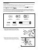
ASSEMBLY Assembly requires two persons. Place all parts of the exercise cycle in a cleared area and remove the packing materials. Do not dispose of the packing materials until assembly is completed. Assembly requires the included tools and your own adjustable wrench driver , and pliers . , Phillips screw- Use the part drawings below to identify the small parts used in assembly. The number in parenthesis below each drawing refers to the key number of the part, from the PART LIST on page 14.
3. The Console (16) requires three AA batteries; alkaline batteries are recommended. Insert three batteries into the battery compartment. Make sure that the batteries are oriented as shown by the markings inside the battery compartment. 3 Batteries 16 4. Hold the Console (16) near the Handlebar (15). Insert the console wire into the indicated hole in the Handlebar. Note: The console wire is longer than shown. 4 16 Attach the Console (16) to the Handlebar (15) with four M4 x 16mm Screws (49).
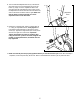
. While another person holds the Upright (13) in the position shown, connect the console wire to the Reed Switch Wire (43). Next, connect the Resistance Cable (19) to the Lower Cable (45) in the following way: 6 Be careful to avoid pinching the wires and cables while inserting the Upright. • See drawing A. Pull up on the metal bracket on the Lower Cable (45), and insert the tip of the Resistance Cable (19) into the wire clip inside the metal bracket as shown. • See drawing B.
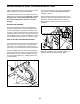
8. Turn the indicated Adjustment Knob (9) counterclockwise and remove it. Insert the Seat Post (5) into the Frame (1). Align one of the adjustment holes in the Seat Post with the indicated hole in the Frame. Insert the Adjustment Knob into the Frame and the Seat Post, and turn the Knob clockwise until it is tight. Make sure that the Knob is inserted through one of the adjustment holes in the Seat Post. 8 5 Adjustment Holes 1 Hole 9 9. Identify the Left Pedal (24), which is marked with an “L.
HOW TO OPERATE THE EXERCISE CYCLE HOW TO ADJUST THE SEAT POST HOW TO ADJUST THE PEDALING RESISTANCE For effective exercise, the seat should be at the proper height. As Seat you pedal, there should be a slight bend in your knees Seat Post when the pedals Hole are in the lowest position. To adjust the height of the Knob seat, first turn the indicated knob counterclockwise and remove it.
FEATURES OF THE CONSOLE 2. Select one of the modes: The easy-to-use console features five modes that provide instant exercise feedback during your workouts. The modes are described below. Scan mode— Mode Indicators When the power is turned on, the scan mode will be selected automatically. A mode indicator will appear below the word “SCAN” to show that the scan mode is selected, and a second mode indicator will show which mode is currently displayed.
MAINTENANCE AND TROUBLESHOOTING Inspect and tighten all parts of the exercise cycle regularly. Replace any worn parts immediately. Next, turn the resistance knob to the lowest setting (see HOW TO ADJUST THE PEDALING RESISTANCE on page 8). To clean the exercise cycle, use a damp cloth and a small amount of mild detergent. Important: To avoid damage to the console, keep liquids away from the console and keep the console out of direct sunlight.
HOW TO ADJUST THE REED SWITCH If the console does not display correct feedback, the reed switch should be adjusted. In order to adjust the reed switch, the left side shield must be removed (see HOW TO ADJUST THE RESISTANCE STRAP on page 10). 43 21 With the left side shield removed, locate the Reed Switch (43). Turn the Crank (21) until the Magnet (38) is aligned with the Reed Switch. Loosen, but do not remove, the M4 x 16mm Screw (49). Slide the Reed Switch slightly closer to or away from the Magnet.
CONDITIONING GUIDELINES The following guidelines will help you to plan your exercise program. Remember that proper nutrition and adequate rest are essential for successful results. mum fat burning, adjust the intensity of your exercise until your heart rate is near the middle number in your training zone as you exercise. Aerobic Exercise WARNING: Before beginning this or any exercise program, consult your physician.
EXERCISE FREQUENCY To maintain or improve your condition, plan three workouts each week, with at least one day of rest between workouts. After a few months of regular exercise, you may complete up to five workouts each week, if desired. Remember, the key to success is make exercise a regular and enjoyable part of your everyday life. SUGGESTED STRETCHES 1 The correct form for several basic stretches is shown at the right. Move slowly as you stretch—never bounce. 1.
EXPLODED DRAWING—Model No. WLEX14820 Key No. Qty. 1 2 3 4 5 6 7 8 9 10 11 12 13 14 15 16 17 18 19 20 21 22 23 24 25 26 1 2 1 4 1 1 2 2 1 5 1 1 1 1 1 1 1 1 1 1 1 1 1 1 1 1 Description Key No. Qty.
EXPLODED DRAWING—Model No.
ORDERING REPLACEMENT PARTS To order replacement parts, call our Customer Service Department toll-free at 1-800-999-3756, Monday through Friday, 6 a.m. until 6 p.m. Mountain Time (excluding holidays).