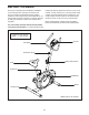
www.weslo.com Model No. WLEX81214.0 Serial No. Write the serial number in the space above for reference. Serial Number Decal ACTIVATE YOUR WARRANTY To register your product and activate your warranty today, go to www.wesloservice.com/ registration. CUSTOMER CARE For service at any time, go to www.wesloservice.com. Or call 1-866-699-3756 Mon.–Fri. 6 a.m.–6 p.m. MT Sat. 8 a.m.–12 p.m. MT Please do not contact the store.
TABLE OF CONTENTS WARNING DECAL PLACEMENT . . . . . . . . . . . . . . . . . . . . . . . . . . . . . . . . . . . . . . . . . . . . . . . . . . . . . . . . . . . . . . .2 IMPORTANT PRECAUTIONS . . . . . . . . . . . . . . . . . . . . . . . . . . . . . . . . . . . . . . . . . . . . . . . . . . . . . . . . . . . . . . . . . . 3 BEFORE YOU BEGIN. . . . . . . . . . . . . . . . . . . . . . . . . . . . . . . . . . . . . . . . . . . . . . . . . . . . . . . . . . . . . . . . . . . . . . . .
IMPORTANT PRECAUTIONS WARNING: To reduce the risk of serious injury, read all important precautions and instructions in this manual and all warnings on your exercise bike before using your exercise bike. ICON assumes no responsibility for personal injury or property damage sustained by or through the use of this product. 1. It is the responsibility of the owner to ensure that all users of the exercise bike are adequately informed of all precautions. 8.
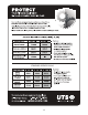
STANDARD SERVICE PLANS all 4
BEFORE YOU BEGIN Thank you for selecting the new WESLO® PURSUIT CT 2.4 exercise bike. Cycling is an effective exercise for increasing cardiovascular fitness, building endurance, and toning the body. The PURSUIT CT 2.4 exercise bike provides a selection of features designed to make your workouts at home more effective and enjoyable. reading this manual, please see the front cover of this manual. To help us assist you, note the product model number and serial number before contacting us.
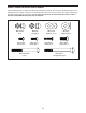
PART IDENTIFICATION CHART Use the drawings below to identify the small parts needed for assembly. The number in parentheses below each drawing is the key number of the part, from the PART LIST near the end of this manual. The number following the key number is the quantity needed for assembly. Note: If a part is not in the hardware kit, check to see if it has been preassembled. Extra parts may be included.
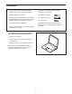
ASSEMBLY • To hire an authorized service technician to assemble this product, call 1-800-445-2480. • In addition to the included tool(s), assembly requires the following tools: • Assembly requires two persons. one Phillips screwdriver • Place all parts in a cleared area and remove the packing materials. Do not dispose of the packing materials until you finish all assembly steps. one adjustable wrench • To identify small parts, see page 6. Assembly may be easier if you have a set of wrenches.
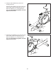
2. Identify the Rear Stabilizer (39), which has Leveling Caps (40). 2 Attach the Rear Stabilizer (39) to the Frame (23) with two M8 x 65mm Carriage Bolts (18), two M8 Curved Washers (17), and two M8 Acorn Nuts (42); insert both Carriage Bolts, and then tighten the Acorn Nuts. 40 39 17 42 17 23 40 18 3.
4. Attach the Seat (45) to the Seat Post (44) with three M8 Locknuts (9) and three M8 Large Washers (49); start all the Locknuts, and then tighten them. 4 45 44 49 9 5. Loosen and remove the Seat Knob (24). 5 Next, insert the Seat Post (44) into the Seat Post Sleeve (26), and then insert the Seat Knob into the Frame (23) and into an adjustment hole in the Seat Post. Move the Seat Post upward or downward slightly to make sure that the Seat Knob is engaged in one of the adjustment holes in the Seat Post.
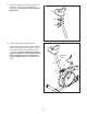
6. While a second person holds the Upright (35) near the Frame (23), connect the Upright Wire (36) to the Reed Switch Wire (7). 6 Next, push the Lower Resistance Cable (34) upward into the Upright (35), and then pull the end of the Lower Resistance Cable out of the indicated hole. Hole 35 34 36 7 23 7. Insert the excess wire and cable into the Frame (23). 7 Tip: Avoid pinching the wire and the cable. Slide the Upright (35) onto the Frame (23).
8. Connect the Resistance Cable (37) to the Lower Resistance Cable (34) in the following way: See drawing A. Pull upward on the metal bracket (A) on the Lower Resistance Cable (34), and insert the tip of the Resistance Cable (37) into the wire clip inside the metal bracket. 8 A A 34 37 See drawing B. Firmly pull the Resistance Cable (37) upward and slide it into the top of the metal bracket (A). See drawing C. Using pliers, squeeze the prongs on the upper end of the metal bracket (A) together.
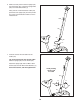
10. Attach the Water Bottle Holder (21) to the Upright (35) with two M5 x 20mm Screws (27); start both Screws, and then tighten them. 10 21 35 27 11. The Console (1) can use two AA batteries (not included); alkaline batteries are recommended. Do not use old and new batteries together or alkaline, standard, and rechargeable batteries together. IMPORTANT: If the Console has been exposed to cold temperatures, allow it to warm to room temperature before you insert batteries.
12. While a second person holds the Console (1) near the Upright (35), connect the wire on the Console to the Upright Wire (36). 12 1 Tip: Avoid pinching the wires. Attach the Console (1) to the Upright (35) with four M5 x 10mm Screws (2); start all the Screws, and then tighten them. 36 35 Avoid pinching the wires 2 13. Identify the Right Pedal (33). 13 Using an adjustable wrench, firmly tighten the Right Pedal (33) clockwise into the right side of the Crank (3).
HOW TO USE THE EXERCISE BIKE HOW TO ADJUST THE SEAT POST HOW TO ADJUST THE PEDALING RESISTANCE For effective exercise, the seat should be at the proper height. As you pedal, there should be a slight bend in your knees when the pedals are in the lowest position. To increase the resistance of the pedals, turn the resistance knob clockwise; to decrease the resistance, turn the knob counterclockwise.
CONSOLE DIAGRAM FEATURES OF THE CONSOLE The easy-to-use console features five modes that provide instant exercise feedback during your workouts. Scan (SCAN)—This mode displays the time, speed, distance, and calorie modes, for a few seconds each, in a repeating cycle. Time (TMR)—This mode displays the elapsed time. Note: If you set a time goal (see step 2 on page 16), this display will show the time remaining in your workout. Speed (SPD)—This mode displays your pedaling speed, in miles per hour.
HOW TO USE THE CONSOLE 3. Begin pedaling and follow your progress with the displays. Make sure that batteries (not included) are installed in the console (see assembly step 11 on page 12). If there is a sheet of plastic on the console, remove the plastic. Scan mode—To select the scan mode, press the MODE button repeatedly until the word SCAN appears in the display. 1. Turn on the console.
FCC INFORMATION This equipment has been tested and found to comply with the limits for a Class B digital device, pursuant to part 15 of the FCC Rules. These limits are designed to provide reasonable protection against harmful interference in a residential installation. This equipment generates, uses, and can radiate radio frequency energy and, if not installed and used in accordance with the instructions, may cause harmful interference to radio communications.
MAINTENANCE AND TROUBLESHOOTING MAINTENANCE Locate the Reed Switch (7). Turn the Crank (3) until a Magnet (12) is aligned with the Reed Switch. Inspect and tighten all parts of the exercise bike regularly. Replace any worn parts immediately. To clean the exercise bike, use a damp cloth and a small amount of mild detergent. IMPORTANT: To avoid damage to the console, keep liquids away from the console and keep the console out of direct sunlight.
HOW TO ADJUST THE DRIVE BELT If you can feel the pedals slip while you are pedaling, even when the resistance is at the highest level, the drive belt may need to be adjusted. To adjust the drive belt, you must first remove the right pedal and the right shield as described below. Using an adjustable wrench, turn the right pedal counterclockwise and remove it. Next, see the EXPLODED DRAWING on page 23.
EXERCISE GUIDELINES Aerobic Exercise—If your goal is to strengthen your cardiovascular system, you must perform aerobic exercise, which is activity that requires large amounts of oxygen for prolonged periods of time. For aerobic exercise, adjust the intensity of your exercise until your heart rate is near the highest number in your training zone. WARNING: Before beginning this or any exercise program, consult your physician.
SUGGESTED STRETCHES The correct form for several basic stretches is shown at the right. Move slowly as you stretch; never bounce. 1. Toe Touch Stretch Stand with your knees bent slightly and slowly bend forward from your hips. Allow your back and shoulders to relax as you reach down toward your toes as far as possible. Hold for 15 counts, then relax. Repeat 3 times. Stretches: Hamstrings, back of knees and back. 1 2. Hamstring Stretch Sit with one leg extended.
PART LIST Key No. Qty. 1 2 3 4 5 6 7 8 9 10 11 12 13 14 15 16 17 18 19 20 21 22 23 24 25 26 1 4 1 2 1 1 1 1 5 1 2 2 2 1 2 2 10 4 2 1 1 4 1 1 2 1 Model No. WLEX81214.0 R1115A Description Key No. Qty.
EXPLODED DRAWING Model No. WLEX81214.
ORDERING REPLACEMENT PARTS To order replacement parts, please see the front cover of this manual.