
Owner's manual
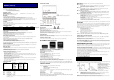


Dimensions in mm
* includes gasket
1/16 & 1/32 DIN TEMPERATURE CONTROLLER
MANUAL (59423-6)
MECHANICAL INSTALLATION
The Controllers are designed to be mounted either in a 1/16 or a 1/32 DIN panel cutout. The units are sleeve mounted with the front
bezel assembly rated NEMA4/IP66 provided that:
− the panel is smooth and the panel cutout is accurate;
− the mounting instructions are carefully followed.
DIN PANEL CUTOUT
1/16 DIN: 45.0mm +0.6 / 0.0 wide, 45.0mm +0.6 / 0.0 high 1/32 DIN: 45.0mm +0.6 / -0 wide, 22.2mm +0.3 / -0 high
Maximum panel thickness 9.5mm
Minimum spacing 20mm vertical, 10mm horizontal
MOUNTING
To mount a Controller proceed as follows:
1 Check that the controller is correctly orientated and then slide the unit into the cutout.
2 Slide the panel clamp over the controller sleeve pressing it firmly against the panel until the controller is held firmly.
3 The controller front bezel and circuit board assembly can be unplugged from the sleeve. Grasp the bezel firmly by the recesses on
each side and pull. A screwdriver can be used as a lever if required.
4 When refitting the bezel assembly it is important to press it firmly into the sleeve until the latch clicks in order to compress the
gasket and seal to NEMA4X/IP66.
CLEANING
Wipe down with damp cloth (water only)
Note: The controller should be isolated before removing or refitting it in the sleeve, and electrostatic precautions should be observed
when handling the controller outside the sleeve.
DIMENSIONS: MODELS
Model
Bezel
*
Behind panel
Overall
length
Behind panel
length*
Wid
th
Height
Width
Height
1/32 DIN
–
48
x 24mm
51.0
28.5
44.8
22.0
116.2
106.7
1/16 DIN
–
48 x 48mm
51.0
51.0
44.8
44.8
116.2
106.7
ELECTRICAL INSTALLATION
(Also see important Safety Information)
OUTPUT DEVICES
Two of the following output devices are fitted to the controllers, depending on the model.
1 Solid state relay drive (SSd/SSd1/SSd2) 5Vdc +0/-15%, 15mA non isolating. To switch a remote SSR (or logic)
2 Miniature power relay (rLY/rLY1) 2A/250V AC resistive, Form A/SPST contacts.
3 Sub miniature power relay (rLY2) 1A/250V AC resistive, Form A/SPST contacts.
OUTPUT DEVICE ALLOCATION
Any of the available outputs may be chosen for the main setpoint (SP1), the remaining device being automatically allocated to the
second setpoint (SP2).
Dual relay or dual SSd output models are available to order. Please contact your local distributor for details.
Designed for use with the following supply voltages:
1). 100 - 240V 50-60 Hz 4.5 VA (nominal) +/-10% maximum permitted fluctuation
2). 12V - 24V (AC/DC) +/-20% 4.5 VA Polarity not required
The supply voltage is dependant on the specific model, check the product label to establish the correct voltage for the unit.
WIRING THE CONNECTOR
Prepare the cable carefully, remove a maximum of 8mm insulation and ideally tin to avoid bridging. Prevent excessive cable strain.
Maximum recommended wire size: 32/0.2mm 1.0mm
2
(18AWG).
INDUCTIVE LOADS
To prolong relay contact life and suppress interference it is recommended engineering practice to fit a snubber (0.1uf/100 ohms)
between terminals 5 and 6.
CAUTION:Snubber leakage current can cause some electro-mechanical devices to be held ON.
Check with the manufacturers specifications.
EN61010 - /CSA 22.2 No 1010.1 92
− Compliance shall not be impaired when fitted to the final installation.
− Designed to offer a minimum of Basic Insulation only.
− The body responsible for the installation is to ensure that supplementary insulation suitable for Installation Category II or III is
achieved when fully installed.
− To avoid possible hazards, accessible conductive parts of the final installation should beprotectively earthed in accordance with
EN6010 for Class 1 Equipment.
− Output wiring should be within a Protectively Earthed cabinet.
− Sensor sheaths should be bonded to protective earth or not be accessible.
− Live parts should not be accessible without the use of a tool.
− When fitted to the final installation, an IEC/CSA APPROVED disconnecting device should be used to disconnect both LINE and
NEUTRAL conductors simultaneously.
− A clear instruction shall be provided not to position the equipment so that it is difficult to operate the disconnecting device.
− These products are intended for indoor use only.
SENSOR SELECTION
Thermocouples
Description
Sensor Range
Linearity
tC b
tC E
tC J
tC K
tC L
tC n
tC r
tC s
tC t
Pt
-
30% Rh/Pt
-
6%Rh
Chromel/Con
Iron/Constantan
Chromel/Alumel
Fe/Konst
NiCrosil/NiSil
Pt-13% Rh/Pt
Pt-10% Rh/Pt
Copper/Con
0 to 1800
°
C
0 to 600°C
0 to 800°C
-50 to 1200°C
0 to 800°C
-50 to 1200°C
0 to 1600°C
0 to 1600°C
-200 to 250°C
2.0
*
0.5
0.5
0.25*
0.5
0.25*
2.0*
2.0*
0.25
Resistan
ce Thermometer RTD
Pt100/RTD
-
2
-
200 to 400
°
C
0.25
*
Linear process inputs (Input mV range: 0 to 50mV)
Displays 0 - 20mV 4 - 20mV setpoint limits
Lin1 0 - 100 0 – 400 ± 0.5%
Lin2 0 - 100 -25 - 400 ± 0.5%
Lin3 0 - 1000 0 - 3000 ± 0.5%
Lin4 0 - 1000 -250 - 3000 ± 0.5%
Lin5 0 - 2000 0 - 3000 ± 0.5%
Notes: 1 Linearity: 5-95% sensor range
2 * Linearity B:5° (70º - 500°C) K/N:1° >350°C exceptions: R/S: 5°<300°C T:1° <- -25° >150°C
RTD/Pt100: 0.5° <-100°C
CONNECTION DIAGRAM
SAFETY INFORMATION
INSTALLATION
Designed for use:
UL873 - only in products where the acceptability is determined by Underwriters Laboratories Inc.
EN61010-1 / CSA 22.2 No 1010.1 - 92
To offer a minimum of Basic Insulation only.
Suitable for installation within Category II and III and Pollution Degree 2.
SEE ELECTRICAL INSTALLATION It is the responsibility of the installation engineer to ensure this equipment is installed as
specified in this manual and is in compliance with appropriate wiring regulations.
Field wiring must be rated for a minimum of 70 deg C
CONFIGURATION
All functions are front selectable, it is the responsibility of the installing engineer to ensure that the configuration is safe. Use the
program lock to protect critical functions from tampering.
ULTIMATE SAFETY ALARMS
Do not use SP2 as the sole alarm where personal injury or damage may be caused by equipment failure.
INSTRUMENT PANEL FEATURES
Green Display: Process temperature or program Function/Option
Orange Display: Setpoint temperature or program Option (Dual Display only)
Green LED: Setpoint 1 output indicator
Red/Orange LED: Setpoint 2 output indicator
ADJUSTMENTS
To enter or exit program mode: Press ▲ ▼ together for 3 seconds
To scroll through functions: Press ▲ or ▼
To change levels or options: Press ▲ together or ▼ together
To view setpoint: Press
To increase setpoint: Press ▲ together
To decrease setpoint: Press ▼ together
To reset an alarm or fault condition: Press ▲ ▼ together briefly
Notes: If in difficulty by becoming “lost” in program mode, press ▲ and ▼ together for 3 seconds to return to
display mode, check the INSTRUMENT ADJUSTMENTS above and try again.
When in program mode, after 60 seconds of key inactivity the display will revert to either inPt : nonE or, if the
initial configuration has been completed, the measured value. Any settings already completed will be retained.
GETTING STARTED
After power-up the controller requires programming with the following information:
− Type of Sensor
− Operating unit
− Allocation of Output Device to SP1/SP2 (Relay or SSd)
− Temperature Setpoint
When the above information has been programmed into the controller it will be operational with the following factory settings.
Proportional band/Gain 10ºC/18ºF
Integral time/Reset 5 mins
Derivative time/Rate 25 secs
Proportional cycle-time 20 secs (Typical setting for relay output)
DAC Derivative approach control 1.5 (Average setting for minimum overshoot)
NOTE: The instruments covered in this manual may be fitted with either a single or a dual display. Where a single display
shows more than one reading, it will alternate between them.
INITIAL SET-UP
On power-up the controller will display the self test sequence followed by the initial display inPt : none
Select input sensor.
− Press and hold
and use the
▲
or
▼
buttons to scroll through the sensor selection list until the correct sensor is
displayed. Release the buttons. The display will now read selected sensor type e.g. inPt : tCs
− Press
▲
once The display will now read unit : none
Select unit.
− Press and hold
and use the
▲
or
▼
buttons to scroll through the unit selection list until the correct unit is
displayed. Release the buttons. The display will read selected unit e.g. unit : °C
− Press
▲
once The display will now read SP1.d : nonE
Select SP1 (Main setpoint output device)
Note: Dual Relay and Dual SSd Output Options Models have their outputs pre-configured. Move to Step 4.
− Press and hold
and use the
▲
or
▼
buttons to select SSd or rLY as required. The controller will now read
selected output device e.g. SP1.d : SSd
To enter initial configuration into controller memory
− Press and hold both
▲
and
▼
buttons for 3 seconds. The display will now read ParK and measured variable
(temperature) (eg. 23 ) ParK is displayed because a setpoint has not yet been entered.
− To display setpoint
Press and hold
The displays will now read unit (eg. °C ) and 0
− To enter setpoint
Press and hold
and use
▲
button to increase or
▼
button to decrease the reading and scroll to required setpoint
value. (The digit roll-over rate increases with time).
THE CONTROLLER IS NOW OPERATIONAL WITH FACTORY SETTINGS
Note: For precise control of an application the controller may need to be TUNED. Please see the following section on AUTOTUNE
AUTOTUNE
This is a single shot procedure to match a controller to the process. Select either Tune or Tune at Setpoint from the criteria below.
The Tune program should be used when the load temperature is at or near ambient. The procedure will apply disturbances when
the temperature reaches 75% of the setpoint value, causing overshoot which is monitored in order to adjust the DAC overshoot
inhibit feature. Care should be taken to ensure that any overshoot is safe for the process.
The Tune at Setpoint program is recommended when:
− The process is already at setpoint and control is poor
− The setpoint is less than 100°C
− Re-tuning after a large setpoint change
− Tuning multi-zone and/or heat-cool applications.
Notes: DAC is not re-adjusted by Tune at setpoint.
Proportional Cycle Time can be pre-selected before running the Autotune program.
Hereafter the symbol (
▲▼
) signifies both buttons are held pressed for 3 seconds to ENTER or EXIT program mode.
TUNE OR TUNE AT SETPOINT PROGRAM
Enter program (
▲ ▼
) and from the display tunE : oFF press and hold
and press
▲
to display tunE : on or tunE : At.SP
Exit program mode (
▲ ▼
).
The TUNE program will now start. The display will show tunE as the process temperature climbs to setpoint.
Note: During tuning, the main setpoint (SP1) LED will flash.
When the TUNE or TUNE AT SETPOINT program is complete the PID values are entered automatically. The process temperature
will rise to setpoint and control should be stable. If not, this may be because optimum cycle time is not automatically implemented.
To set the cycle time see PROPORTIONAL CYCLE-TIME.
PROPORTIONAL CYCLE-TIME
The choice of cycle-time is influenced by the external switching device or load. eg. Contactor or SSR. A setting that is too long for a
process will cause oscillation or a setting that is too short will cause unnecessary wear to an electro-mechanical switching device.
Factory set - To use the 20 sec factory set cycle-time no action is needed whether autotune is used or not.
To Manually Select AUTOTUNE Calculated CYCLE-TIME
When AUTOTUNE is completed, enter program (
▲ ▼
) and select CYC.t in Level 1. The display will read CYC.t:20 (factory setting)
To view the new calculated optimum value, press and hold both
and
▼
buttons until indexing stops. The calculated value will be
displayed eg. A16. If acceptable, exit program (
▲ ▼
) to implement this setting.
To Pre-select Automatic Acceptance of AUTOTUNE Calculated CYCLE-TIME
Before AUTOTUNE is initiated select CYC.t in Level1, press and hold both
and
▼
buttons until indexing stops at A – –. Exit
program (
▲ ▼
) to accept calculated value automatically.
To Manually Pre-select Preferred CYCLE-TIME
Before AUTOTUNE is initiated select CYC.t in Level 1, press and hold both
and
▲
or
▼
buttons until indexing stops at
preferred value then exit program (
▲ ▼
) to accept.
CYCLE
-
TIME RECOMMENDATIONS
Output device
Factory setting
Recommended minimum
Internal relay : rLY / rLY1 / rLY2 20 seconds 10 seconds
Solid state drives : SSd / SSd1 / SSd2 20 seconds 0.1 seconds
PROGRAMMER -
RAMP-SOAK
This feature enables the controller to ramp up or down from current temperature to a target setpoint at a pre-determined rate. It then
controls at the target setpoint for an adjustable soak period before switching off the SP1 output.
− Set Setpoint ramp rate (0 to 9995 deg/hour)
− From SPrr in Level 1, press and hold
and
▲
or
▼
to scroll to required ramp rate.
− Set Soak (if required) 0 to 1440 minutes
− From SoAk – – in Level 1, press and hold
and
▲
or
▼
to scroll to required Soak time.
− Set Ramp on (Off: On: Hold)
− From Sprn in Level 1, press and hold
, then
press
▲
to select On
− Exit program (
▲ ▼
) to enter settings into
memory and commence ramp to target setpoint.
Notes: In Ramp on configuration, if power is removed from the controller, the Ramp will re-start when power is restored.
The Ramp hold option suspends the ramp at its last value.
If no Soak period has been set, control at target setpoint continues indefinitely.
SP2 deviation alarms follow the ramp setpoint and can be used to alarm “out of limits” ramp rate.
WARNING: The Soak timer is triggered when the ramp setpoint reaches the target setpoint. If the ramp rate is set too fast for the
process, the Soak timer will be triggered before the process temperature reaches the target setpoint.
S1
F1
F1 Fuse:
1A time lag type to IEC127. CSA/UL rating
250Vac
S1 Switch: IEC/CSA/UL Approved disconnecting
device