
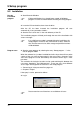
Instruction Manual

4 Configuration parameters
72
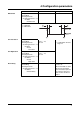
Event traces
Input signal Configuration
➔ Recording
➔ Event traces
➔ Event traces 1 — 6
➔ Input signal
Off,
Bin. inp. 1 — 4,
Logic channel 1 — 6,
Low alarm 1 — 6,
Low comb.al.,
High alarm 1 — 6,
High comb.al,
Count/Int/Al 1 — 6,
C/i. comb.al.,
Comb. alarm,
CF inserted,
IntMemAlmCF,
IntMemAlmSer,
MemAlmCFcard,
Error, Modbus flag,
The event (digital signal)
which is to be recorded is
assigned to an event trace
here.
Event traces 5 and 6 are
switched off in the factory
setting.
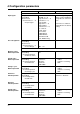
Trace designation Configuration
➔ Recording
➔ Event traces
➔ Event traces 1 — 4
➔ Trace design.
7 characters
BE 1 — 4
Operating modes
Memory status:
Normal operation
Configuration
➔ Recording
➔ Normal operation
➔ Memory status
Off,
On
Stored value:
Normal operation
Configuration
➔ Recording
➔ Normal operation
➔ Stored value
Average val.,
Instant val.,
Minimum,
Maximum,
Peak value
v Chapter 2.7 “Operating
modes”
Chapter 2.8 “Storing
data”
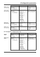
Storage cycle:
Normal operation
Configuration
➔ Recording
➔ Normal operation
➔ Storage cycle
1—60 — 32767s v Chapter 2.7 “Operating
modes”
Chapter 2.8 “Storing
data”
Start time:
Timed operation
Configuration
➔ Recording
➔ Timed operation
➔ Start time
any time Off when
Start time = End time
End time:
Timed operation
Configuration
➔ Recording
➔ Timed operation
➔ End time
any time
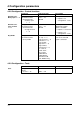
Stored value:
Timed operation
Configuration
➔ Recording
➔ Timed operation
➔ Stored value
Average val.,
Instant val.,
Minimum,
Maximum,
Peak value
v Chapter 2.7 “Operating
modes”
Chapter 2.8 “Storing
data”
Parameter Value/Selection Description