
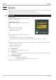
Instruction Manual
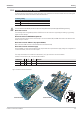


I-6.8 Connecting diagram i/o-modules
(Modular Option C)
+
CAN and modular option C are mutually precluding.
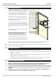
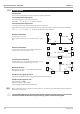
The inputs and outputs of multi-function unit KS98-1 can be adapted to the individual application by means of “modu
-
lar optionC". The supporting card is firmly installed in the unit.
The card contains four sockets for various I/O modules which can be combined, whereby the positions of the various
connection types are dependent on engineering.
The KS98-1 programming personnel must provide a connecting diagram corresponding to the block diagram ( r page )
for installation of the device.
Electrical connections - Safety hints 9499-040-82711
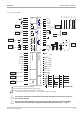
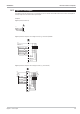
I-28 Connecting diagram i/o-modules
Resistive input
(9407-998-0x201)
TC, mV, mA / V inputs
(9407-998-0x211) /
(9407-998-0x221)
Voltage / current outputs
(9407-998-0x301) /
(9407-998-0x311)
Combined digital inputs/ outputs
(9407-998-0x401)
Frequency/ Counter inputs
(9407-998-0x241)
_
_
_
_
_
_
U1
I1
U2
I2
I1
I2
+
+
+
+
+
+
di 1/2 (-)
di 2 (+)
di 1 (+)
do 1/2 (-)
do 2
do 1
do1/2(+)
_
_
U1
U2
+
+
+
+
R1
R1
R1
R2
R1
R2
}2
}1
di 2 (+)
di 1 (+)
di 1/2 (-)
di 2 (+)
di 1 (+)
di 1/2 (-)
di 2 (+)
di 1 (+)
di 1/2 (-)
di 2 (+)
di 1 (+)
di 1/2 (-)
V
V
4-wire 3-wire 2-wire Poti
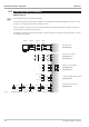
Fig. 10 Quadruple counter up/down counter 2 x counter and2xfrequency