
Instruction Manual
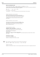

X0, X100 application principle
Configurations X0, X100 are used in different ways dependent on the input type:
w
Current input: X0, X100 are scaling values of the signal source (e.g. temp. transmitter): 0 mA = X0, 20 mA = X100.
w
Potentiometric transducer input: X0, X100 are the user-specific calibration values. Within range X0, X100, display
of 0...100% input signal is required.
w
Temperature difference input: X0, X100 contain the lead resistance values after calibration by the user: X0 is the
lead resistance of connected sensor 1. X100 is the lead resistance of connected sensor 2.
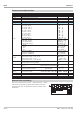
X0 and X100 are parameters of function block AINP1, i.e. part of the engineering.
This means that the user calibration remains unchanged after replacing the unit, if it was reloaded into the engineering
after calibration.
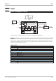
%Wert
XAIOL
AI AIOL
=
-
-1
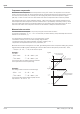
Standard 0/4...20 mA current input
The input resistance is 50 [
During configuration, distinction of 0...20 mA and 4...20 mA is made. For 4 ... 20 mA standard signal, the signal behav
-
iour with sensor break can be determined (Fail). Additionally, physical input signal scaling using a defined value of
X0 and X100 is possible. For measured value processing, a filter time constant with a numeric value between 0,0
and 200000 can be adjusted (r Tfm)
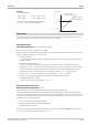
0/2...10 V voltage signal input
The input resistance is ? 100 k[
During configuration, distinction of 0...10 V and 2...10 V is made. For 2 ... 10 V standard signal, the signal behaviour
with sensor break can be determined (Fail). Additionally, physical input signal scaling with a defined value of X0
and X100 is possible. For measured value processsing, a filter time constant with a numeric value within 0,0 and
200000 can be adjusted (r Tfm)
9499-040-82711 Inputs
AINP1 ( analog input 1 (No. 08)) III-280