
Instruction Manual

Input 6 to which a potentiometric transducer is connected features a particularity: only the wiper resistance rather
than the overall resistance is measured. For this reason, the internal parameter setting and calculation of the input 6
transducer is not identical with the one of input 1.
These calibration values belong to the engineering, i.e. when replacing the instrument, the user calibration remains un
-
changed. As a prerequisite, it has to be re-loaded into the engineering after calibration.
Standard 0/4...20 mA current input
The input resistance is 50 [
During configuration, distinction between 0...20 mA and 4...20 mA is made. For standard 4 ... 20 mA signal, the signal
behaviour with sensor break can be defined (Fail). Additionally, physical input signal scaling using a defined value
of X0 and X100 is possible. For measured value processing, a filter time constant with a numeric value within 0,0
and 200000 can be adjusted (r Tfm)
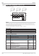
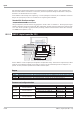
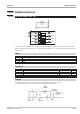
III-17.4 DINPUT ( digital inputs (No. 121))
Function ‘DINPUT’ is used for digital input configuration and parameter setting. The function is assigned firmly to block
number 91 and is calculated invariably in each time slot. Inversion of each individual signal can be configured. If in -
puts di3...di12 are provided is dependent of the KS 98-1 hardware option.
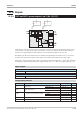
Outputs
Digital outputs:
z1...z2 Signal at digital input di1 or di2 (Digital inputs di1 and di2 are available in each unit also without options).
z3...z7 Signal at digital input di1 or di2 (Digital inputs di3 to di7 are only provided with option B).
z8...z12 Signal at digital input di1 or di2 (Digital inputs di8 to di12 are only provided with option C).
Parameter and configuration data
Parameter Description Values Default
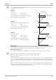
Inv1
Transfer behaviour
direct output direct
t
inverted output inverse
Inv2
Transfer behaviour
direct output direct
t
inverted output inverse
:
:
:
:
:
:
:
:
:
:
Inv12
Transfer behaviour
direct output
direct
t
inverted output
inverse
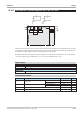
Inputs 9499-040-82711
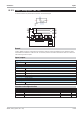
III-285 DINPUT ( digital inputs (No. 121))
HARDWARE
SOFTWARE
di1
di2
di3
di4
...
di12
z1
z2
z3
z4
...
z12
Inv1