Form 3803 • Price $15.00 Edition 1 • © Dec.
I nformation in this installation, wiring, and operation manual is subject to change without notice. One manual is provided with each instrument at the time of shipment. Extra copies are available at the price published on the front cover. Copyright © December 1997, The Partlow-West Company, all rights reserved.
TABLE OF CONTENTS SECTION 1 - OVERVIEW 1.1 1.2 1.3 1.4 1.5 Display Control Alarms Digital Communications Power Input SECTION 2 - INSTALLATION & WIRING 2.1 2.2 2.3 2.4 Unpacking Location / Mounting Preparation for Wiring Wiring Connections SECTION 3 - NORMAL OPERATION 3.1 3.2 3.3 3.4 Changing The Chart Control Output Settings Alarm Settings High/Low Limits PAGE NUMBER 5 5 5 5 5 5 6 6 6 8 11 15 15 15 16 16 SECTION 4 - RECORDER SETUP, TEST, AND CALIBRATION 16 4.
FIGURES Figure 2-1A Panel Mounting 6 Figure 2-1B FIgure 2-1C Surface Mounting Adaptor Plate 7 7 Figure 2-2 Noise Suppression 9 Figure 2-3 Figure 2-4 Noise Suppression Board and Terminal Locations 9 11 Figure 2-5A Figure 2-5B AC Power Input Wiring-Standard Voltage Power Wiring-Low Voltage 12 12 Figure 2-6 Input Signal Wiring 12 Figure 2-7 Figure 2-8 Relay Output Wiring Communications Wiring 13 13 Figure 2-9A Figure 2-9B Transmitter Power Supply (One Transmitter) Transmitter Power Supply
Section 1 Overview This instrument records process trend lines, one or two pens, on a 10 inch circular chart. As an option, up to two alarm points are provided for each of the two pens. This recorder will accept J, K, T, R, and S Thermocouples and RTD inputs, as well as typical Millivolt, Milliamp (4-20mA) and Volt inputs, (up to 5 volts). 1.1 DISPLAY Process values for each pen can be displayed on the .56" LED display, or the display can be blanked.
Section 2 Installation and Wiring Read these instructions completely and carefully before proceeding with the installation and operation of this recorder. Electrical code requirements and safety standards should be observed. Installation should be performed by qualified personnel only. Caution: The standard recorder will accept a power input over the range of 90-264 VAC. There is a special low power voltage option that is available.
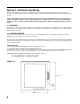
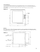
SURFACE MOUNTING: 1. Loosen the mounting brackets attached to the recorder and flip their position so the ears are flush with the back of he recorder. Fasten the recorder to the surface using the appropriate fasteners (#10 screws or nuts and bolts) depending on the surface material. 2. As an alternative, remove the brackets, attach them to the surface, and then attach the recorder to the brackets.
2.3 PREPARATION FOR WIRING Electrical noise interference is a phenomenon typical of industrial environments. Use the following guidelines which are generally used to minimize the effect of electrical noise on instrumentation in general. 2.3.
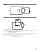
FIGURE 2-2 C Inductive Load MOV A.C. R FIGURE 2-3 MOV A.C. R C Inductive Load 2.3.1 SENSOR PLACEMENT If the input probe will be subjected to corrosive or abrasive conditions, it should be protected by the appropriate thermowell. The probe should be positioned to reflect the true process temperature: In liquid media - the most agitated area In air - the best circulated area For thermocouple sensors, the lead resistance should not exceed 300 ohms.
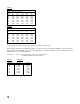
TABLE 1 Temperature error in °C per 1000 feet of Lead wire AWG Thermocouple Type: No. J K T R S 10 0.03 0.09 0.04 0.10 0.11 12 0.05 0.13 0.06 0.16 0.16 14 0.09 0.21 0.10 0.27 0.26 16 0.14 0.34 0.15 0.41 0.42 18 0.22 0.55 0.25 0.68 0.68 20 0.36 0.86 0.39 1.08 1.09 24 0.88 2.19 0.99 2.72 2.73 TABLE 2 Temperature Error in °F per 1000 feet of Lead wire AWG Thermocouple Type: No. J K T R S 10 0.06 0.15 0.07 0.18 0.19 12 0.10 0.24 0.11 0.30 0.30 14 0.16 0.39 0.18 0.48 0.48 16 0.25 0.61 0.28 0.75 0.75 18 0.40 0.
2.4 WIRING CONNECTIONS WARNING: Avoid electrical shock. AC power wiring must not be connected at the source distribution panel until all wiring connections are completed. All wiring connections are typically made to the instrument at the time of installation. All connections are made behind the access door on the recorder right side. Loosen the two thumbscrews and open the access door to complete all wiring.
2.4.1 ELECTRICAL CONDUIT OPENINGS The instrument case has 3 conduit openings, all on the right hand side of the case. To minimize the effect of electrical noise, the following wire groups should be routed through the conduit openings as shown below. Top Conduit Opening - Power Input - TB1 Middle Conduit Opening - Input Signal Wiring & Communications - TB2, TB3, and TB4 Bottom Conduit Opening - Optional Control/Alarm Outputs - Option Board TB5-TB8 Note: Unused conduit openings should be sealed. 2.4.2.
2.4.4 RELAY OUTPUT WIRING Relay outputs, up to 2 for each pen, are provided as an option on this instrument with a separate circuit board that is mounted in the lower right hand corner of the instrument, near the lower electrical conduit hole. Wire up each relay as shown in Figure 2-7.
2.4.6 TRANSMITTER POWER SUPPLY WIRING Connections are made as shown using TB10, terminal 2 as positive (+) and terminal 1 as negative (-). See Figure 2-9A for one transmitter and Figure 2-9B for two transmitters (40mA DC maximum).
Section 3 Normal Operation Assuming that the MODE switch (discussed later) is in the RUN position, on power up, the recorder will display the software revision, in the format rX.XX, while the pens move to the home position (toward the center of the chart). Then the instrument will display the model number. Only the first 8 digits will be displayed, 4 digits at a time, for two seconds each. Then the display will blank while the recorder is measuring the input(s).
3.2 CONTROL OUTPUT SETTINGS 3.2.1 SINGLE OUTPUT When Single Output On/Off control is configured as CH (Control Heat), the relay will turn OFF when the process value is greater than the setpoint by one-half the hysteresis value and turn ON when the process value is less than the setpoint by one-half the hysteresis value.
3.3 ALARM SETTINGS There are two possible alarm set point values for each of the two possible inputs/pens. They will be displayed only if the alarm options are present and configured. The types of alarms and the ability to make alarm set point changes, is defined during configuration. See Section 4 to select the types of alarms and to allow/disable alarm changes. TO REVIEW/MODIFY ALARM SETTINGS Repeatedly depress the SCROLL key. If any alarms exist, the alarm LED (ALRM 1/1, ALRM 1/2, etc.
4.1 HARDWARE SELECTIONS - INPUT JUMPER POSITIONS Hardware jumpers JU1 and JU2 are used to select the input type for Pen 1 and Pen 2 respectively. The jumper positions are shown on the main wiring label on the recorder as well as on the Short Form Programming Card. See below: JU1 and JU2 Positions - JU1 is located between wiring terminals TB2 and TB3 on the edge of the main board. JU2 is located between wiring terminals TB3 and TB4 on the same board. RTD and Millivolt 5 VDC Milliamp Thermocouple 4.
These parameters apply to each pen, assuming pen 2 is present, and are configured in each respective section.
ChUP Value that equates to upper chart division -9999 to 9999* 100 ChLO Value that equates to Lower chart division -9999 to 9999 0 HySt Hysteresis or Switch differential for outputs in units, not percent (will show only if outputs present) 0 to 200* 3 dFF Display Filter Factor Filters display for input noise. Higher number means more filtering.
4.3 TEST MODE - TEST To enter the Test mode, press SCROLL until tESt shows on the display. Press DOWN to enter the Test mode. Press SCROLL to display the various tests (diSP and Chrt). Press DOWN to enter a test section. 4.3.1 Display, Keypad, and Relay Test - diSP Once you enter the Display/Keypad/Relay test by depressing DOWN, the display should first show all 8s with decimal points and all status LEDs lit for about 5 seconds. Then the display will go blank for 5 seconds. Then the display will show SCrL.
Section 5 Recorder Calibration Mode - CAL As covered in Section 4, the "calibration seal" may need to be removed to access the MODE switch to gain access to the calibration section. The MODE switch must be positioned to the PROG/TEST/CAL position. CAUTION: DO NOT ATTEMPT ANY CALIBRATIONS WITHOUT THE PROPER TEST EQUIPMENT THAT MEETS OR EXCEEDS THE SPECIFICATIONS LISTED. The Calibration mode provides for the calibration of all the input types for each input as well as the calibration of each pen to the chart.
3=Milliamp for all milliamp ranges. 4=RTD for all RTD ranges. 5=Cold Junction Compensation for all T/C ranges. After selecting the proper range code, depress the SCROLL key and rEF should be displayed. With rEF displayed, depress the SCROLL key to display the value for the source to be connected. Connect the input source set for this value to the selected input terminals. After connecting the source, depress the SCROLL key and SCAn should be displayed.
PEN ARC MECHANICAL ADJUSTMENTS - ArC Important Note: Pen arc adjustments have been done at the factory and should not need to be done in the field, unless the pen arm adjustments (mechanical) have been compromised. (This can happen if the pens are forcibly moved.) Adjustments can be made at the bottom or top of span. In either position, the arm "length" can be adjusted by moving the pen blade toward or away from the pivot point, but the pen tip should also line up with the inner or outer ring of the chart.
Appendix A - Model Number Matrix 5 1 2 4 FIRST PEN OPTION Recorder Only Controller High/Low Limit* 0 1 2 4 SECOND PEN OPTION None Recorder Only Controller High/Low Limit* 0 1 2 PEN 1 OUTPUTS None One Alarm Relay Two Alarm Relays 0 1 2 PEN 2 OUTPUTS None One Alarm Relay Two Alarm Relays Blank AA 1 2 3 4 0 1 2 3 1 2 3 SUFFIX None Alarms And Communications Connectivity Option (Allows for later field installation of both options) VOLTAGE Standard (90-264 VAC) Low Voltage** Standard Voltage Operati
Appendix B - Specifications INPUTS Input Types/Range Thermocouple RTD Current DC Voltage DC Impedance RTD Excitation Current Input Scan Rate Input Correction Sensor Fault Detection Type Range J 0°C to 760°C 0°F to 1400°F K 0°C to 1360°C 0°F to 2500°F T -200°C to 400°C -330°F to 750°F R 200°C to 1650°C 400°F to 3000°F S 200°C to 1650°C 400°F to 3000°F 100 ohm Platinum -140°C to 400°C -220°F to 750°F .00385 ohms/ohm/°C 0 to 20mA, 4 to 20mA Internal 4.
RECORDING Pen Type Pen Color Chart Size Chart Drive Chart Rotation Chart Span Disposable fiber tip Pen 1 - Red Pen 2 - Green 10 inch Stepper motor User configurable: 8 hours, 12 hours, 24 hours, 48 hours, or 7 days Bottom and top of span, -9999 to 9999 units RECORDING PERFORMANCE Chart Recording Accuracy Chart Rotation Accuracy 0.5% of chart span reference accuracy ± 0.5% of rotation time, assuming all backlash removed OPERATOR INTERFACE Display Status Indicators Keypad Display Modes Four digit, 0.
TRANSMITTER POWER SUPPLY Transmitter Power Supply Provides up to 40mA of current at 24VDC CONSTRUCTION Enclosure NEMA Rating Conduit Openings Mounting Overall Dimensions Panel Cutout Panel Depth Panel Protrusion Weight Retrofit Injection molded Noryl case and cover with acrylic window NEMA 3 standard, NEMA 4X future option Three openings on the right side Panel or wall 14" wide X 14" high X 3.8" deep. (355.6mm X 355.6mm X 96.5mm) 12.7" wide X 12.7" high (322.58mm X 322.58mm) 2.5" (63.5mm) 1.3" (33.
NOTES 1. Linearization accuracy is based on conformance to NIST Monograph 175 (based on the ITS-90) for letter-designated thermocouple types, or other industry standards for RTDs. 2. Factory Calibration is defined by limits of repeatability in a manufacturing environment and ± 0.
NOTES
Warranty and Return Statement These products are sold by The Partlow-West Company under the warranties set forth in the following paragraphs. Such warranties are extended only with respect to a purchase of these products, as new merchandise, directly from The PartlowWest Company or from a Partlow Brand distributor, representative or reseller, and are extended only to the first buyer thereof who purchases them other than for the purpose of resale.
THE PARTLOW-WEST COMPANY 2 CAMPION ROAD • NEW HARTFORD, NY 13413 USA 1-800-866-6659 • 315-797-2222 • FAX 315-797-0403