
Manual

13
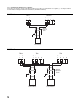
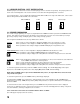
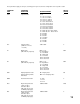
2.4.4 RELAY OUTPUT WIRING
Relay outputs, up to 2 for each pen, are provided as an option on this instrument with a separate circuit board that is mounted
in the lower right hand corner of the instrument, near the lower electrical conduit hole. Wire up each relay as shown in Figure
2-7.
FIGURE 2-7
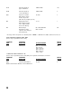
2.4.5 COMMUNICATIONS WIRING
Connections for the Communications option are made to the Main board via the TB4 connections. See Figure 2-8 for wiring.
FIGURE 2-8
1
2
3
TB5 - Pen 1, Alarm 1
Normally Closed
Common
Normally Open
1
2
3
TB6 - Pen 1, Alarm 2
Normally Closed
Common
Normally Open
1
2
3
TB7 - Pen 2, Alarm 1
Normally Closed
Common
Normally Open
1
2
3
TB8 - Pen 2, Alarm 2
Normally Closed
Common
Normally Open
Alarm Option
Board
1
2
3
TB4 - Communications
-
+
Shield