
Installation Guide
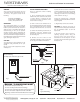

Fig. 1
Air Hose to Controller
Electrical Rating
15 Amps (non-inductive) @120 V AC
WARNING - TO AVOID RISK OF INJURY
- Use indoors in dry locations only.
- Do not exceed specied electrical ratings.
- Do not crimp or damage the interconnecting air hose.
- No user servicable components inside controller.
- Opening controller will void manufacturer’s warranty
GENERAL
This controller system provides safe and
convenient remote on/o switching of one
120 V load. The system consists of the
following:
Controller, P/N SAFPAC27
Air Transmitter, P/N MPT-3428
Air Hose, 6 feet, P/N TU7-006
OPERATION
The control system works on a sealed air
displacement principle. As the air transmitter
button is pressed and released, sealed air is
displaced and is transmitted through the
interconnecting air hose, to the pressure
sensitive electrical switch, completing the
electrical circuit and turning the disposer on.
The circuit will remain energized until the air
transmitter button is depressed and released
again, turning the disposer o.
CAUTION:
To avoid damage to this equipment, or the
equipment being controlled, do not cycle
rapidly.
Do not connect other equipment to outlet
with disposer.
Fine Decorative Plumbing Since 1935
WESTBRASS
Fine Decorative Plumbing Since 1935
WESTBRASS
2429 E Olympic Blvd., Los Angeles, CA 90021 • (213) 627-8441 • FAX (213) 627-2844 • info@westbrass.com • www.westbrass.com
ASB Installation Instructions
Fig. 2
Transmitter
Button
Air Hose
To Transmitter
Threaded Body
Mounting Nut
Silicone
or Gasket
INSTALLATION INSTRUCTIONS
Read all instructions before installing
control system.
1) The air transmitter must be mounted
within 6 feet of the controller outlet. Select
a location which is convenient for user
operation and easily accessible for service
and/or removal. See Fig. 3
2) Drill a 1-1/4” to 1-3/8” diameter hole at
the transmitter mounting location selected.
The air transmitter body can be mounted
through surfaces from 1/16 in. to 2 in. thick.
3) Remove the mounting nut from the air
transmitter. Insert the threaded body
through the mounting hole and re secure
the mounting nut.
4) Connect one end of the air hose
(supplied) to the tting on the air transmit-
ter. See Fig. 2 for additional information.
5) Route the air hose to the controller in a
convenient path where it will not be kinked,
cut, or become disconnected. Attach the
remaining end of the air hose to the tting
on the controller. See Fig. 1.
6) Plug the controller into a dedicated,
grounded, 120 V AC outlet which is continu-
ously energized.
7) Plug the disposer into the controller.
CAUTION: The disposer may begin to
operated. If it does, simply press and release
the air transmitter button to turn the
disposer o.
8) Be sure that the control system is
operating properly before using the
disposer. Press and release the air
transmitter to turn the disposer on. Press
and release the air transmitter again to turn
the disposer o.
Disposer
Power Cord
Fig. 3
Typical Mounting
Air
Hose
Controller
Receptical
Continuously
Energized
Mount Transmitter
on Sink, Countertop,
Wall or Cabinet