
User Manual


Installation and Operator Handbook DRB-25 Diagnostics Monitor
AMX-MA-00656 Issue 0.02 (USA) 3
4. Double-click on the file “setup.exe”. For floppy disk distributions this will be a top-level file, for
CDROMS it may be located in a subdirectory named “disk1”.
5. Follow the instructions given by the Setup dialog boxes.
If installation problems occur then contact the supplier.
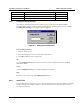
6.2.4 Starting DRB-25 Diagnostic Monitor for the First Time
To start the DRB-25 Diagnostic Monitor, select the ZDM icon from the Start | Programs menu.
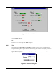
The DRB-25 Diagnostic Monitor main window will appear as shown in Figure 6.1.
Figure 6-1 DRB-25 Diagnostic Monitor Main Window
6.2.5 Connecting the DRB-25 Diagnostic Monitor to the Controller Module
To connect to a Controller Module:
1. A DRB-25 Programming Cable (ADI Part number AMX-CB-02272) is required. Connect the PC
communications port to be used to the DRB-25 Controller Module RJ-11 serial port connector using the
cable.
2. The DRB-25 Diagnostic Monitor will attempt to automatically establish communications with the
Controller Module. If this is successful the status dialog boxes will open automatically. If not the
Configure Comms dialog box will be opened.
3. Using the procedure given in Section “Configuring Communications”, set the PC communications port
used to connect to the DRB-25, and the PC communication parameters required for the Controller Module.